
Flux Reference Manual

  • Welcome to Flux
  • Introduction
    • Installing the software
    • The user interface
    • Part workflow
  • CAD
    • 2-D Import
      • 2-D Cleanup
    • 3-D Import
      • Import 3D Model
      • Import assembly
      • Form detection
      • Component detection
    • Modifying the geometry
    • Attachments
  • Laser CAM
    • Part workflow
      • Editing panels
        • Laser cut
          • Approach
          • Withdrawal
          • Microjoint
          • Advanced
        • Contour
        • Scrap cut
        • Part
        • Corner treatment
      • Quick-Nest
    • Job workflow
      • Job panel
        • Sheets tab
        • Parts tab
        • Layouts tab
        • Summary tab
      • Edit layout
        • Nesting modes
        • Placement panel
        • Sequencing
        • Slice sheet
    • Bevel cut
      • Open contours
      • Variable bevel
      • Miscellaneous
    • Advanced
      • Finishing rules
      • Edit LTT
      • FlyLine
      • TwinLine
        • Strategy
        • Microjoints
        • Further settings
      • DetectLine
  • Bend CAM
    • Create bend data
    • Bend navigator
    • Edit bend data
      • Edit a bend
      • Edit a tool mount
      • Edit a bend setup
      • Edit the back-gauges
      • Edit angle measurement
      • Bends spreadsheet
      • Changing the sequence
      • Adding setups and stations
    • Advanced
      • Angle measurement
      • Batch process
      • Recompute solution
      • Tonnage check
    • Bending Aids
  • BendMaster CAM
    • Bend navigator
    • Part pickup
      • Pickup from pallet
      • Pickup from dispenser
    • Robotic bending
      • Insertion
      • Bending
      • Extraction
    • Regripping
      • Regrip panel
      • Add regrip
      • Edit regrip
      • Regrip with jaw
      • RG-Stations panel
    • Part deposit
      • Deposit panel
      • Repeat and sequence
      • Add separator sheets
      • Lock part-rest
      • Deposit pattern types
    • Advanced
      • Waypoints
      • Cell configuration
      • Custom Cell Components
      • Gripper database
        • Create a gripper
        • Import gripper from DXF
        • Import Suction Cup
  • FlexCell CAM
    • Bend navigator
    • Part pickup
      • Pickup from pallet
      • Centering table
    • Robotic bending
      • Insertion
      • Bending
      • Extraction
      • Advanced
    • Regripping
      • Regrip panel
      • Add/Remove regrip
      • Gripper Panel
      • RG-Stations panel
    • Part deposit
      • Deposit panel
      • Deposit Tabs
    • Advanced
      • Waypoints
      • Cell configuration
      • Gripper database
        • Create a gripper
        • Import gripper from DXF
    • Troubleshooting
  • Fold CAM
    • Create fold data
    • The Fold view
    • Editing Fold data
      • Edit a bend
      • Edit a side/section
      • Change the sequence
      • Edit the blank-holders
      • Edit the gauging
      • Edit the blades
      • Edit the loading
      • Edit the unloading
    • Tool inventory
    • Advanced
      • Custom air-gap tables
      • Manual bend completion
      • Required flange length
  • Settings
    • Drawing
      • Layers
      • Dimensions
      • View
    • Bend CAM
      • Machine defaults
      • Bend outputs
      • Bend view
      • Bend cell
    • Cut CAM
      • Layout
        • Nest settings
        • Sheet
        • Sheet handling
        • Skeleton cuts
        • Work support
      • Laser CAM
        • Sequence
      • Cut outputs
      • Cut view
    • Panel bending
      • Defaults
      • ZBW carriers
      • Outputs
    • Reports
      • Item defaults
    • Import/Export
    • Environment
  • Database
    • Materials
    • Machines
    • Bend tools
    • Bend deductions
    • Bend grippers
    • Forms and Components
  • Reports
    • Report designer
    • Fields, pictures and tables
    • Bands (sub-reports)
    • Labels, bitmaps and shapes
  • Appendix
    • Supported 3D formats
    • Separator sheet DXF
    • Bend tool DXF
    • The Adapt Geometry feature
FlexCell CAM
/
Troubleshooting

Troubleshooting

This is a troubleshooting guide that provides a concise, icon-driven reference to diagnose and fix common issues while doing simulation in the FlexCell CAM. Each table below shows an icon, its meaning, and practical steps to resolve the condition — use the "Methods to resolve the error" column as your primary action list.

Provided below a sample of Bend navigator table with errors:
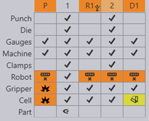
errorbendnavig

  • Bend navigator can be opened by pressing the Z key.

  • For each bend, the navigator displays several rows of status icons.

    • Icons in uncolored cells → No Errors/Warnings

    • Icons in Orange colored cells → Indicate Errors

    • Icons in Yellow colored cells → Indicate Warnings

  • By clicking on a cell that displays error/warning, it takes you to the simulation stage where those specific error/warning occurs.

1. Punch Row

Icon Meaning Methods to resolve the error

correct

No error

-

span short

Punch span too short

Adjust punch length.

missing

No Punch

Mount punch.

explosion

Punch collides with part

Change/Adjust the tool to avoid collision;
Try changing the bend sequence.

explosion3

Punch collides with die

Change/Adjust the tool to avoid collision.
Make sure to choose either punch or die with less height.

overload

Punch is overloaded beyond its rated tonnage.

A taller punch must be used or add an adapter.

tool short

Punch height is too short

Adjust the tonnage load. Tooltip shows the actual load.

overtravel warning

Punch extends out of the press beam

Adjust punch length, make sure it does not exceed the press beam.

2. Die Row

Icon

Meaning

Methods to resolve the error

correct

No error

-

span short

Die span too short

Adjust die length.

missing

No Die

Mount die.

explosion

Die collides with part

Change/Adjust the tool to avoid collision; Try changing the bend sequence

explosion3

Die collides with Punch

Change/Adjust the tool to avoid collision. Make sure to choose either punch or die with less height.

overload

Die overloaded

Change the tool having V width greater than the previous die.
For 1mm sheet thickness - 8mm V width
2mm sheet thickness - 16mm V width

3. Guage Row

Icon Meaning Methods to resolve the error

correct

No error

-

missing

No back gauges

Position the gauges properly against the part.

explosion3

Back gauge collides with punch or die or part.

Adjust the gauge X position.

4. Machine Row

Icon Meaning Methods to resolve the error

correct

No error

-

explosion3

Part collides with floor

It can be adjusted but lifting the component. But it should not be done.

overtravel

Back-gauge position exceeds the travel limits

Position the gauges within the limits.
NOTE: There should be 200 mm gap between 2 gauges.

explosion

Robot collides with machine table

Make sure that the robot hand is away from the machine. Try changing waypoints, joint rotation.

overload

Machine overloaded

Adjust the thickness of the part.

5. Clamp Row

Icon Meaning Methods to resolve the error

correct

No error

-

missing warning

Tool not clamped properly

Make sure the clamp is holding the tool properly. Adjust the clamp position.

6. Robot Row

Icon Meaning Methods to resolve the error

correct

No error

-

infeasible

Infeasible position (Kinematic error)

Infeasible position is that robot cannot reach or achieve the specified position. To rectify infeasible position error,
Go to the Waypoints globe → Display → In robot axis → Change the drastically varied joint values to its nearest value by observing its previous phase and the upcoming phase. Values can be edited by giving ± 360 to those specific joint values to get the nearest value.

overtravel

Robot axis overtravel

It can be resolved by changing the interpolate → Linear to Axis or vice versa; insert waypoints and adjust values.

explosion

Robot collides with machine components

Move the waypoints to adjust the travel path.
NOTE: Travel path has to away from the components to avoid collision.

7. Gripper Row

Icon Meaning Methods to resolve the error

correct

No error

-

explosion

Gripper collides with cell components

Adjust gripper position to avoid collision.

Gripper collides with floor

Adjust gripper position to avoid collision.

grippercollision

No material under suction cup

Adjust gripper position to ensure material is under suction cup.

overload

Gripper overloaded

Change the gripper according to the part.

8. Cell Row

Icon

Meaning

Methods to resolve the error

correct

No error

-

explosion

Robot collides with cell components

Adjust waypoints to avoid collision.

Gripper collides with cell components

Adjust gripper position to avoid collision.

Gripper collides with floor

Adjust gripper position to avoid collision.

depositunstable

Deposit stack unstable

Ensure the deposit stack is stable by adjusting the deposit position.

Contents

  • 1. Punch Row
  • 2. Die Row
  • 3. Guage Row
  • 4. Machine Row
  • 5. Clamp Row
  • 6. Robot Row
  • 7. Gripper Row
  • 8. Cell Row
Import gripper from DXF Fold CAM

      Copyright © 2025 TRUMPF Metamation. All rights reserved.

    Compiled by Bento