Flux Reference Manual

  • Welcome to Flux
  • Introduction
    • Installing the software
    • The user interface
    • Part workflow
  • CAD
    • 2-D Import
      • 2-D Cleanup
    • 3-D Import
      • Import 3D Model
      • Import assembly
      • Form detection
      • Component detection
    • Modifying the geometry
    • Attachments
  • Laser CAM
    • Part workflow
      • Editing panels
        • Laser cut
          • Approach
          • Withdrawal
          • Microjoint
          • Advanced
        • Contour
        • Scrap cut
        • Part
        • Corner treatment
      • Quick-Nest
    • Job workflow
      • Job panel
        • Sheets tab
        • Parts tab
        • Layouts tab
        • Summary tab
      • Edit layout
        • Nesting modes
        • Placement panel
        • Sequencing
        • Slice sheet
    • Bevel cut
      • Open contours
      • Variable bevel
      • Miscellaneous
    • Advanced
      • Finishing rules
      • Edit LTT
      • FlyLine
      • TwinLine
        • Strategy
        • Microjoints
        • Further settings
      • DetectLine
  • Bend CAM
    • Create bend data
    • Bend navigator
    • Edit bend data
      • Edit a bend
      • Edit a tool mount
      • Edit a bend setup
      • Edit the back-gauges
      • Edit angle measurement
      • Bends spreadsheet
      • Changing the sequence
      • Adding setups and stations
    • Advanced
      • Angle measurement
      • Batch process
      • Recompute solution
      • Tonnage check
    • Bending Aids
  • BendMaster CAM
    • Bend navigator
    • Part pickup
      • Pickup from pallet
      • Pickup from dispenser
    • Robotic bending
      • Insertion
      • Bending
      • Extraction
    • Regripping
      • Regrip panel
      • Add regrip
      • Edit regrip
      • Regrip with jaw
      • RG-Stations panel
    • Part deposit
      • Deposit panel
      • Repeat and sequence
      • Add separator sheets
      • Lock part-rest
      • Deposit pattern types
    • Advanced
      • Waypoints
      • Cell configuration
      • Custom Cell Components
      • Gripper database
        • Create a gripper
        • Import gripper from DXF
        • Import Suction Cup
  • FlexCell CAM
    • Bend navigator
    • Part pickup
      • Pickup from pallet
      • Centering table
    • Robotic bending
      • Insertion
      • Bending
      • Extraction
      • Advanced
    • Regripping
      • Regrip panel
      • Add/Remove regrip
      • Gripper Panel
      • RG-Stations panel
    • Part deposit
      • Deposit panel
      • Deposit Tabs
    • Advanced
      • Waypoints
      • Cell configuration
      • Gripper database
        • Create a gripper
        • Import gripper from DXF
    • Troubleshooting
  • Fold CAM
    • Create fold data
    • The Fold view
    • Editing Fold data
      • Edit a bend
      • Edit a side/section
      • Change the sequence
      • Edit the blank-holders
      • Edit the gauging
      • Edit the blades
      • Edit the loading
      • Edit the unloading
    • Tool inventory
    • Advanced
      • Custom air-gap tables
      • Manual bend completion
      • Required flange length
  • Settings
    • Drawing
      • Layers
      • Dimensions
      • View
    • Bend CAM
      • Machine defaults
      • Bend outputs
      • Bend view
      • Bend cell
    • Cut CAM
      • Layout
        • Nest settings
        • Sheet
        • Sheet handling
        • Skeleton cuts
        • Work support
      • Laser CAM
        • Sequence
      • Cut outputs
      • Cut view
    • Panel bending
      • Defaults
      • ZBW carriers
      • Outputs
    • Reports
      • Item defaults
    • Import/Export
    • Environment
  • Database
    • Materials
    • Machines
    • Bend tools
    • Bend deductions
    • Bend grippers
    • Forms and Components
  • Reports
    • Report designer
    • Fields, pictures and tables
    • Bands (sub-reports)
    • Labels, bitmaps and shapes
  • Appendix
    • Supported 3D formats
    • Separator sheet DXF
    • Bend tool DXF
    • The Adapt Geometry feature
Laser CAM
/
Part workflow
/
Editing panels
/
Contour

Contour

Contour Panel

The Contour panel is used for operations on all the laser cuts on a particular contour. For example, you can add microjoints to split one laser cut into two, or remove joints to combine two consecutive laser cuts on the same contour into one.

To access this panel, click on a laser cut to bring up the Laser Cut panel, and then click on the Contour navigation button near the bottom to open the contour panel.

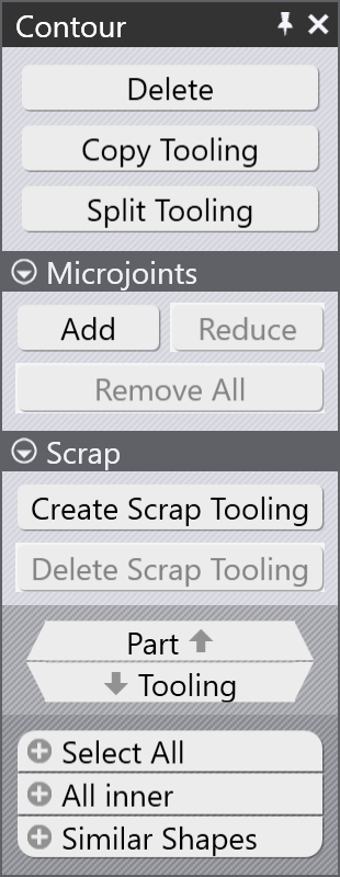
  • Delete: Delete all the laser cuts on this contour.

  • Copy Tooling: Copies the laser cuts on this contour to other similar contours.

  • Microjoint: The settings in this section are used to add or remove microjoints on the contour.

    • Add: Click here to add more microjoints on the contour. Each time a microjoint is added, the existing joints are shifted to make all the laser cuts approximately equal in length. The image below shows the results after successive clicks of the Add button.

      Between the first and second options, the number of laser cuts is not increased, but a microjoint has been added at the end of the cut.
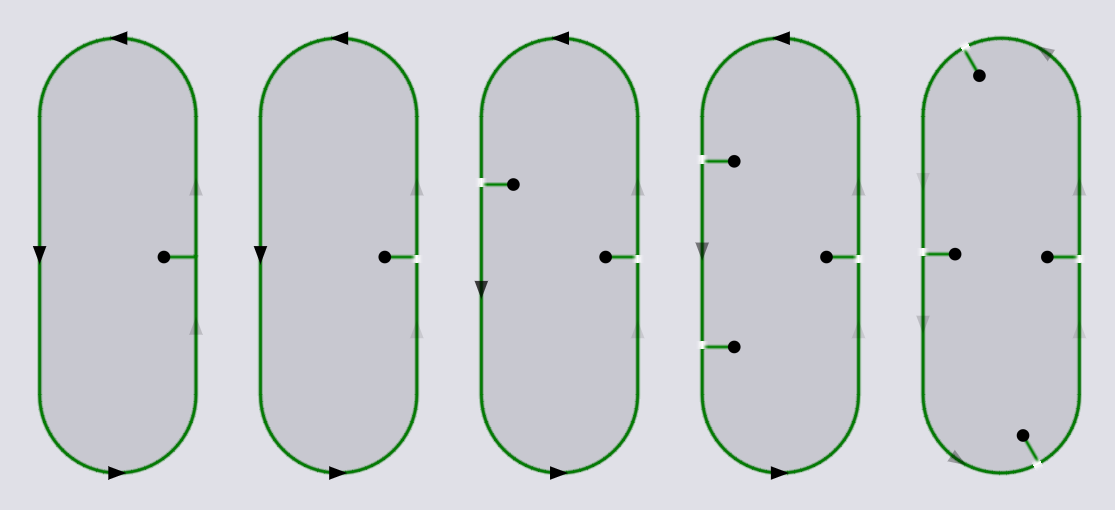
      Add Joints

    • Reduce: Reduce the number of microjoints by combining two laser cuts together.

    • Remove All: Removes all the microjoints on this contour (resulting in a single laser cut cutting the entire contour).

    • Scrap: This section appears if we are inspecting a hole (inner contour), and is used to add Scrap Cuts to slice up the slug created by the hole, or to remove the scrap cuts if they have been added earlier.

Split tooling

Split Tooling

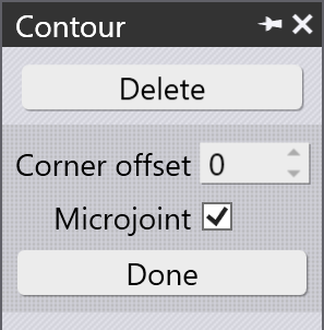
Clicking the Split Tooling switches this panel to a special mode where you can split laser cuts or merge two consecutive laser cuts together interactively.

  • Corner offset: Type in a value here to create a split at a precise distance from a corner. As you move towards this point, a snap indicator appears to help position the split.
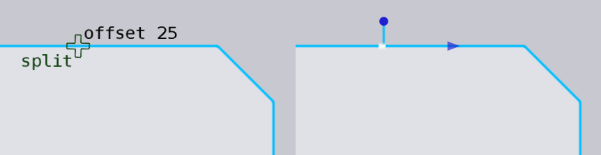
    Corner Offset

  • Microjoint: If this is turned on, a microjoint is created at the split point each time a new laser cut is created. Here is an example of a microjoint being added (since we are at a corner, a corner joint snap indicator is displayed).
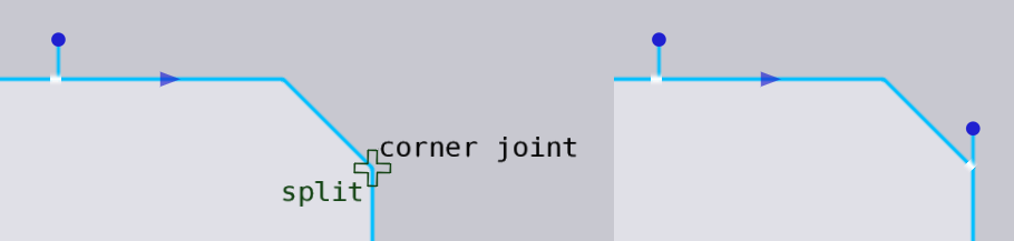
    Corner Joint

You can move the mouse over a microjoint between two cuts, and the snap indicator changes to merge. Clicking will now remove the joint and merge the two adjacent laser cuts together into a single one.
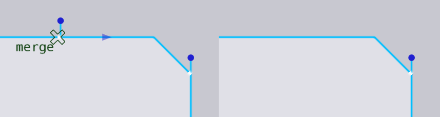
Merge

Contents

  • Split tooling
Advanced Scrap cut

      Copyright © 2025 TRUMPF Metamation. All rights reserved.

    Compiled by Bento