Flux Reference Manual

  • Welcome to Flux
  • Introduction
    • Installing the software
    • The user interface
    • Part workflow
  • CAD
    • 2-D Import
      • 2-D Cleanup
    • 3-D Import
      • Import 3D Model
      • Import assembly
      • Form detection
      • Component detection
    • Modifying the geometry
    • Attachments
  • Laser CAM
    • Part workflow
      • Editing panels
        • Laser cut
          • Approach
          • Withdrawal
          • Microjoint
          • Advanced
        • Contour
        • Scrap cut
        • Part
        • Corner treatment
      • Quick-Nest
    • Job workflow
      • Job panel
        • Sheets tab
        • Parts tab
        • Layouts tab
        • Summary tab
      • Edit layout
        • Nesting modes
        • Placement panel
        • Sequencing
        • Slice sheet
    • Bevel cut
      • Open contours
      • Variable bevel
      • Miscellaneous
    • Advanced
      • Finishing rules
      • Edit LTT
      • FlyLine
      • TwinLine
        • Strategy
        • Microjoints
        • Further settings
      • DetectLine
  • Bend CAM
    • Create bend data
    • Bend navigator
    • Edit bend data
      • Edit a bend
      • Edit a tool mount
      • Edit a bend setup
      • Edit the back-gauges
      • Edit angle measurement
      • Bends spreadsheet
      • Changing the sequence
      • Adding setups and stations
    • Advanced
      • Angle measurement
      • Batch process
      • Recompute solution
      • Tonnage check
    • Bending Aids
  • BendMaster CAM
    • Bend navigator
    • Part pickup
      • Pickup from pallet
      • Pickup from dispenser
    • Robotic bending
      • Insertion
      • Bending
      • Extraction
    • Regripping
      • Regrip panel
      • Add regrip
      • Edit regrip
      • Regrip with jaw
      • RG-Stations panel
    • Part deposit
      • Deposit panel
      • Repeat and sequence
      • Add separator sheets
      • Lock part-rest
      • Deposit pattern types
    • Advanced
      • Waypoints
      • Cell configuration
      • Custom Cell Components
      • Gripper database
        • Create a gripper
        • Import gripper from DXF
        • Import Suction Cup
  • FlexCell CAM
    • Bend navigator
    • Part pickup
      • Pickup from pallet
      • Centering table
    • Robotic bending
      • Insertion
      • Bending
      • Extraction
      • Advanced
    • Regripping
      • Regrip panel
      • Add/Remove regrip
      • Gripper Panel
      • RG-Stations panel
    • Part deposit
      • Deposit panel
      • Deposit Tabs
    • Advanced
      • Waypoints
      • Cell configuration
      • Gripper database
        • Create a gripper
        • Import gripper from DXF
    • Troubleshooting
  • Fold CAM
    • Create fold data
    • The Fold view
    • Editing Fold data
      • Edit a bend
      • Edit a side/section
      • Change the sequence
      • Edit the blank-holders
      • Edit the gauging
      • Edit the blades
      • Edit the loading
      • Edit the unloading
    • Tool inventory
    • Advanced
      • Custom air-gap tables
      • Manual bend completion
      • Required flange length
  • Settings
    • Drawing
      • Layers
      • Dimensions
      • View
    • Bend CAM
      • Machine defaults
      • Bend outputs
      • Bend view
      • Bend cell
    • Cut CAM
      • Layout
        • Nest settings
        • Sheet
        • Sheet handling
        • Skeleton cuts
        • Work support
      • Laser CAM
        • Sequence
      • Cut outputs
      • Cut view
    • Panel bending
      • Defaults
      • ZBW carriers
      • Outputs
    • Reports
      • Item defaults
    • Import/Export
    • Environment
  • Database
    • Materials
    • Machines
    • Bend tools
    • Bend deductions
    • Bend grippers
    • Forms and Components
  • Reports
    • Report designer
    • Fields, pictures and tables
    • Bands (sub-reports)
    • Labels, bitmaps and shapes
  • Appendix
    • Supported 3D formats
    • Separator sheet DXF
    • Bend tool DXF
    • The Adapt Geometry feature
Database
/
Bend tools

Bend tools

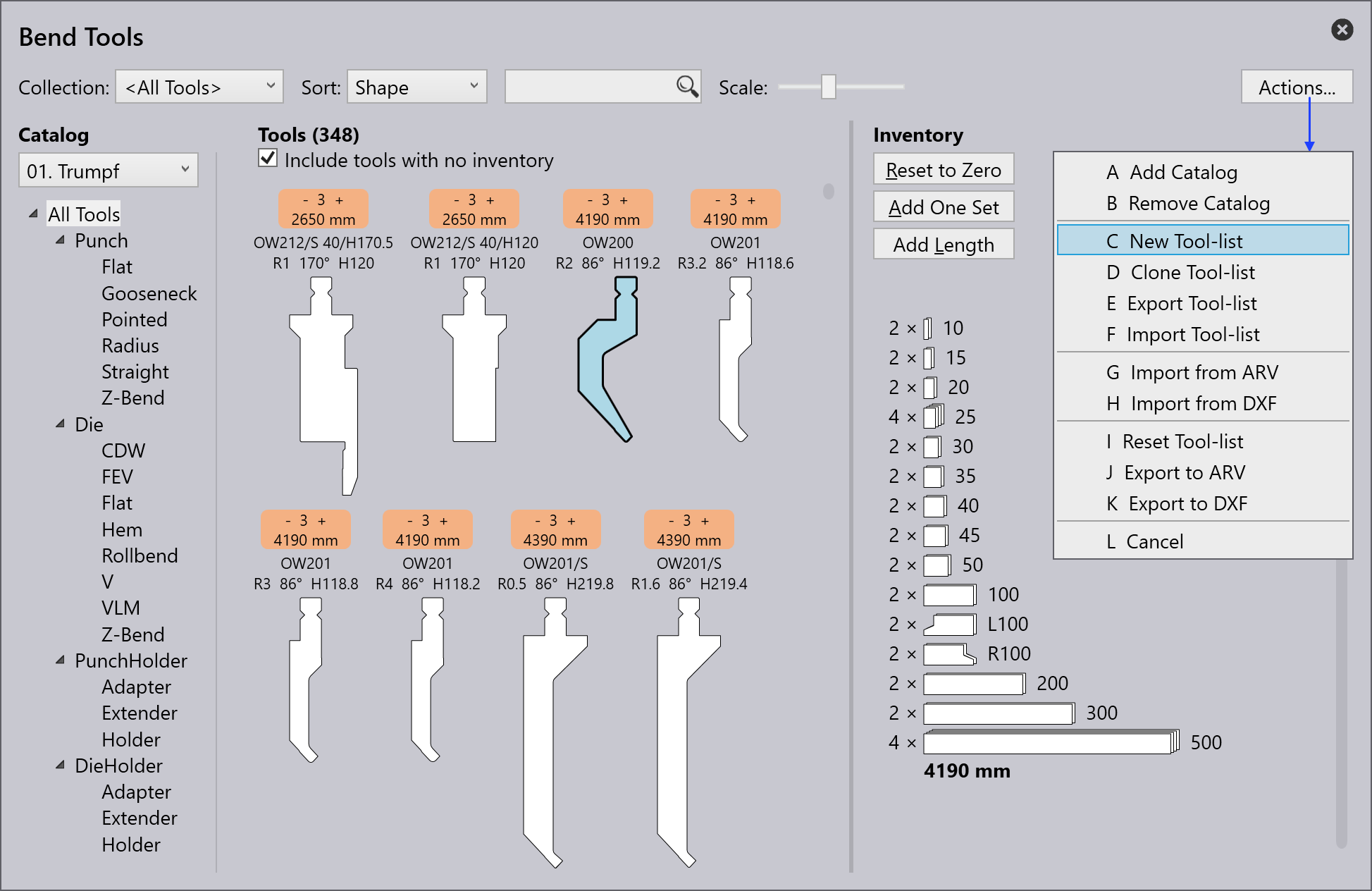
The terms used in bend tool creation are described below:

S.No Term Meaning

1

Tool lists

The tool lists to be worked with can be selected here.New tool lists can be created with the option <New…​>.

2

Sort

The tools can be sorted according to specific criteria here (height, name, shape, radius, angle, die width, priority, tool management).

3

Search

Tools can be searched using the search bar. Here, for example, an alphabetic search can be made for names of tools.

Additionally, more complex search requests can be made. This search request finds all tools with UT or EV in the name which also meet the following conditions: angle ≤ 30, height ≥ 140, height ≤ 220, radius = 1.

4

Scale

The size of the view of the tools can be changed with the slider.

5

Actions

The following actions can be performed:

- A Add catalogue: To add different types of machines.

- B New tool list: To create a new collection of tools.

- C Clone tool list: To clone the created collection of tools.

- D Export tool list: The current tool list can be exported as a ".btools" file.

- E Import tool list: A tool list can be imported as ".btools".

- F Import from ARV: A tool can be imported from an ARV file, these tools are then custom filed in the tool catalog (this will be created if it was not available beforehand).

- G Import from DXF: A tool can be imported from a DXF file. These tools are then custom filed in the tool catalog (this will be created if it was not available beforehand).

- H Reset tool list: Restores the tool list to its default state.

- I Cancel: Closes the Actions…​ window.

6

Tool management

Shows an overview of the selected tool. The following actions can be performed:

  • Reset to zero: The total inventory of the selected tool is removed from the current tool list.

  • Add one set: Only one set of the selected tool is added to the current list.

  • Add length: To add the tool length

  • Add All: The complete inventory of the selected tool is loaded in the current tool list. The inventory is defined in the <All tools> tool list.

  • Save: To save the applied changes.

7

Tool inventory

Displays the inventory of the selected tool. Left mouse-click to add a segment.

8

Tool without inventory

A tool without inventory is not included in the current tool list. By clicking on the empty field a standard inventory for the tool is added and the tool is incorporated into the current tool list.

9

Priority

Based on the priority given by the user,the tool is selected.

1 = High priority tool

5 = Low priority tool

10

Tool display area

In the tool display area, all tools from the selected tool list are displayed. Tools without inventory can also be displayed with the checkbox Include tools with no inventory.

11

Tool filter

Here, the tools of the current tool list are structured according to their type and shape. Selecting an element in this structure enables filtering.

12

Catalog

One of the many tool catalogs installed can be selected with this (including TRUMPF, custom, etc.).

13

Filter condition

The filter condition for the current tool list, which is automatically used by the auto-tooler. This can be used for a named tool list, but not for the special list <All tools>. It is possible to filter according to various aspects, including machine, material, sheet thickness, etc.

Creating a tool list

  1. To create a new tool, list click on the Actions…​ button and select New Tool-List.

    New tool list
  2. Rename the tool list by clicking on the edit icon.

    Rename tool list
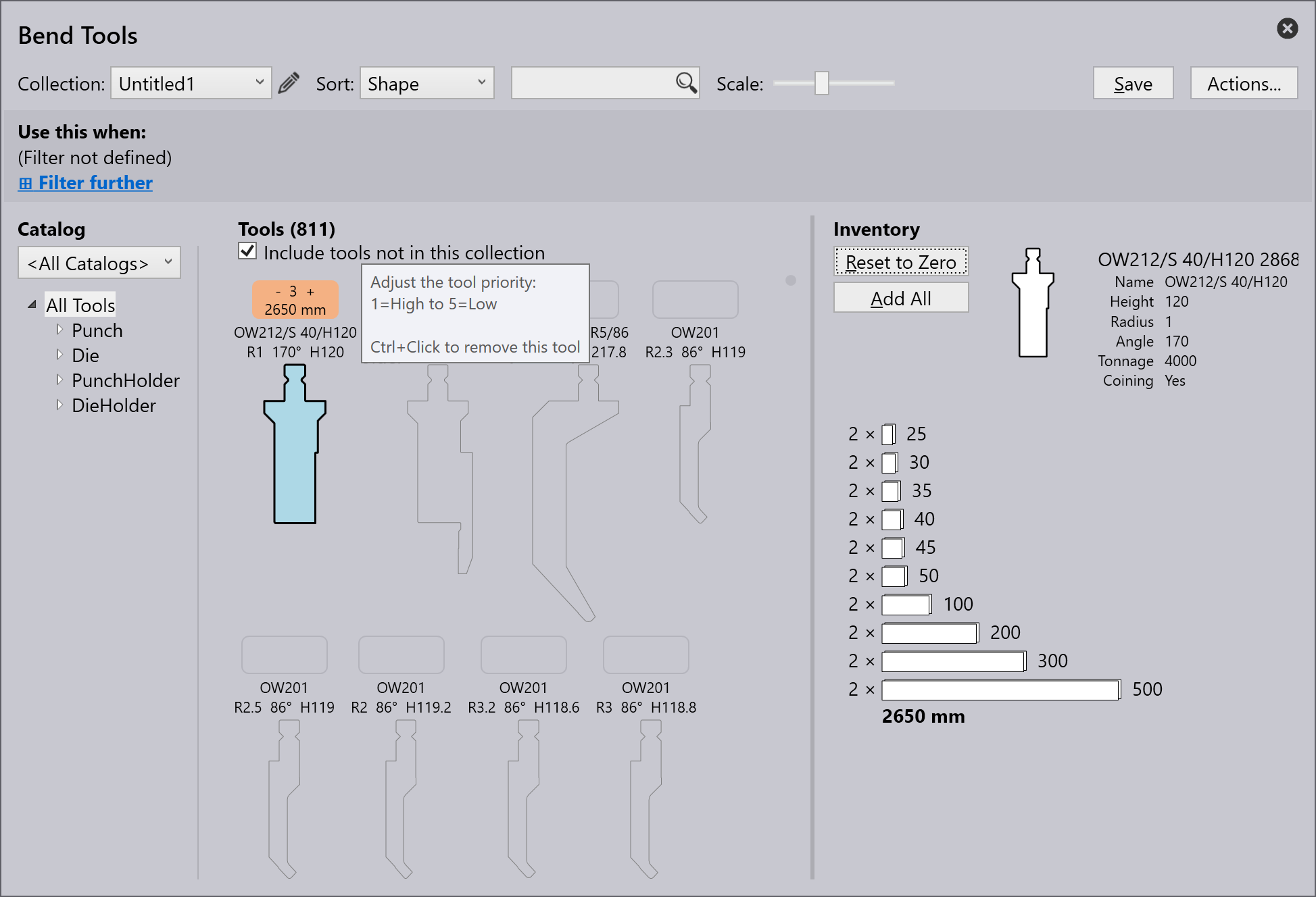
  3. By default, the new tool list displays all tools including Punch, Die, Punch Holder and Die Holder but not added to the inventory. Make sure Include tools not in this collection checkbox is selected.
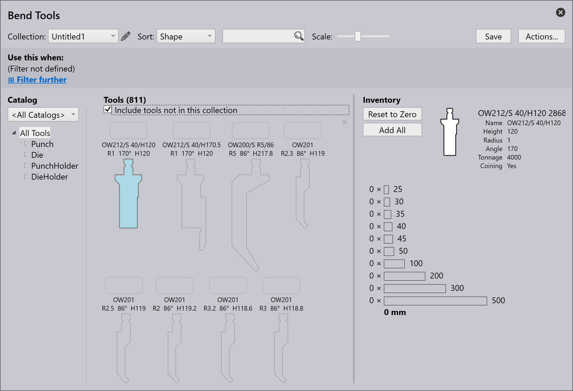
    New catalog
  4. To add a tool, click on the square box above the tool name and ctrl+Enter key to remove a tool.
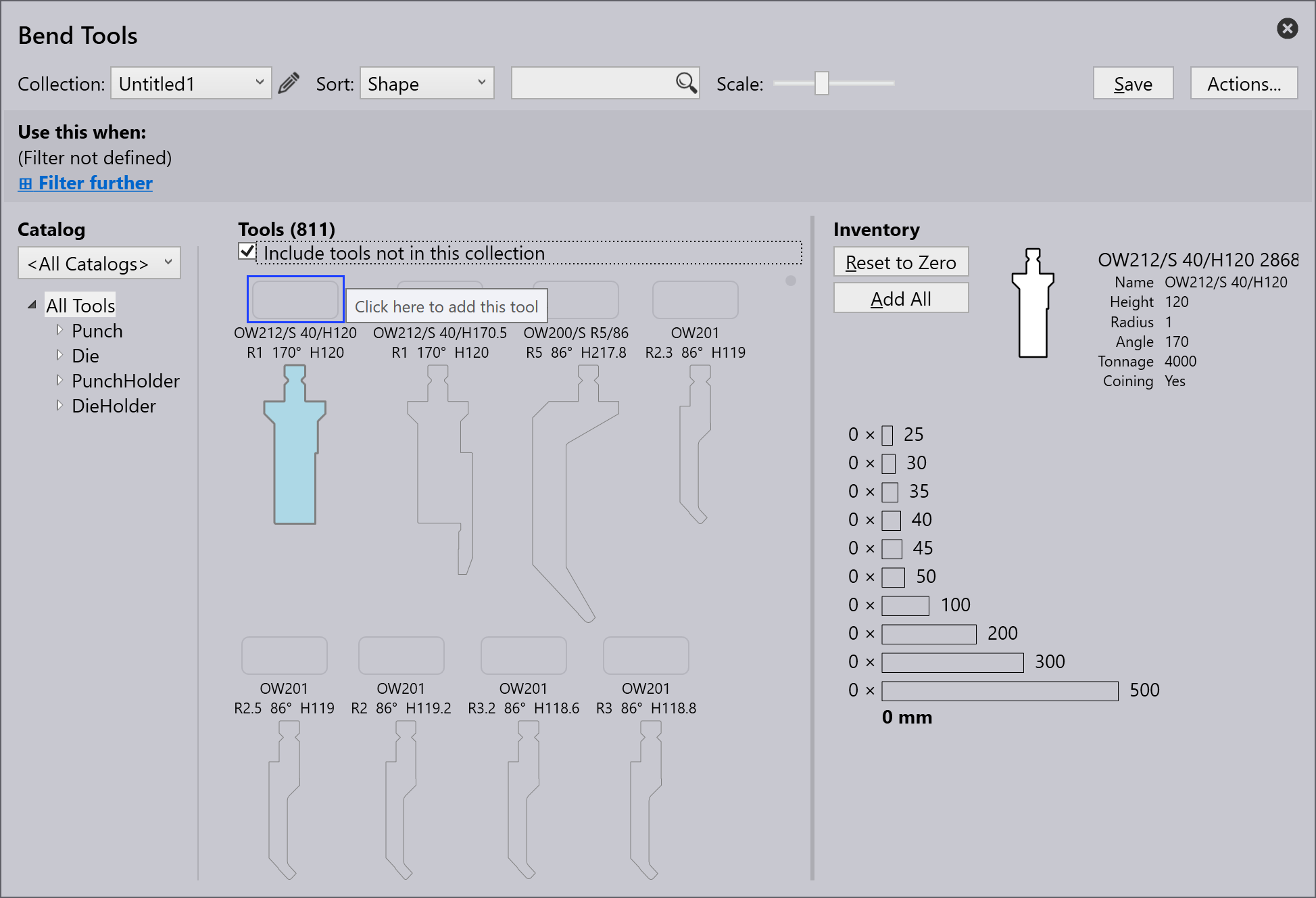
    New catalog
    New catalog with priority
  5. The Use this when: option allows the user to filter and set rules for a new list depending on various criteria.

  6. Click Save to add this tool list to the Collection:.

Adding rule for a tool list

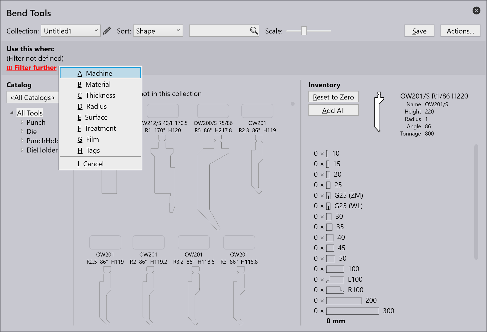
Click the Filter further option to apply a rule from different filter criteria available.

  1. Machine - Refers to the machine used for bending operations.

  2. Material - Denotes the type of substance being bent.

  3. Thickness - Denote the thickness of the material being bent.

  4. Radius - Refers to the curvature of the bend.

  5. Surface - Describe the material’s outer texture or finish.

  6. Treatment - Describe any pre- or post-bending processes applied to the material, such as heat treatment, coating, or galvanization.

  7. Film - Refers to a protective or functional layer applied to the material.

  8. Tags - Custom label assigned to categorize, filter, and organize elements for easier identification.

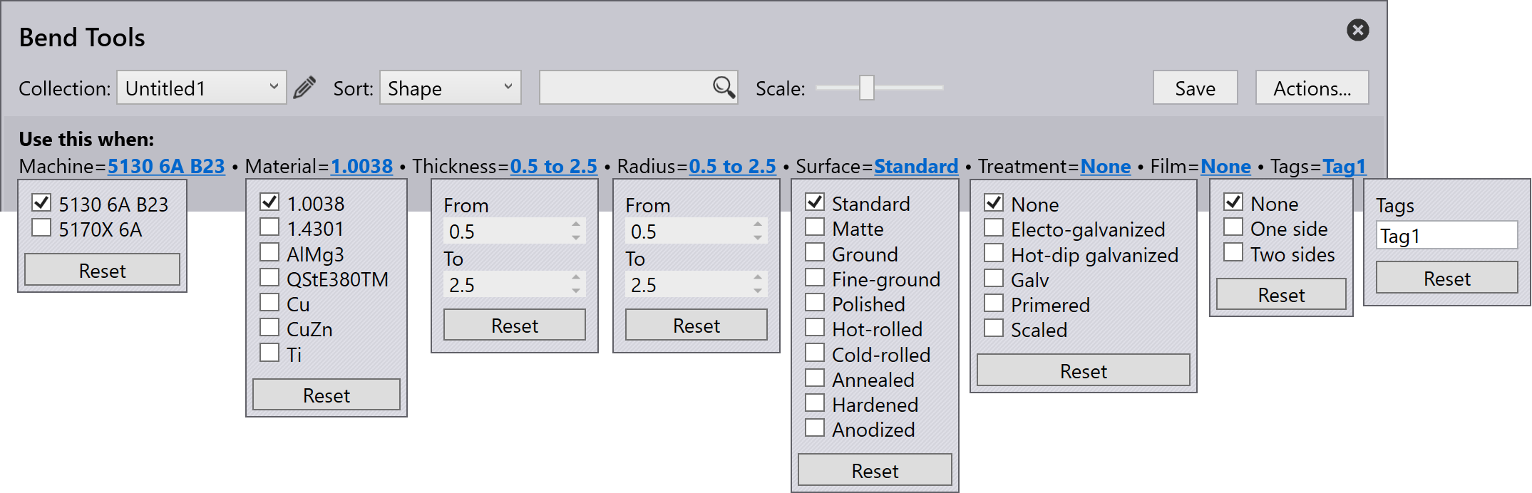
Tool list must have at least one filtering criterion before it can be saved (otherwise this tool list would be used for every part).
Filter

The image below shows an example criteria applied to create a rule:

When multiple tool lists match a specific tooling requirement, the tool list with the most specific match will be used.
Filter types

Contents

  • Creating a tool list
  • Adding rule for a tool list
Machines Bend deductions

      Copyright © 2025 TRUMPF Metamation. All rights reserved.

    Compiled by Bento