
Angle measurement
Angle measurement systems like ACB™, ACBLaser™, or LCB™ can be used to improve the angle accuracy during bending. These systems measure the actual angle achieved during bending and the spring-back of the sheet metal and use this information to adjust the beam bottom-dead-center point dynamically to achieve the target bending angle.
Disk and Laser systems
Angle measurement systems are based on sensor disks mounted in the punches, or on optical systems using a laser beam projected on the workpiece. Flux supports both, and when you configure a machine, there are some option switches that you can turn on, depending on the machine options you have installed.
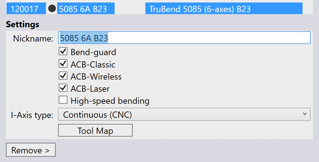
The image above shows a settings panel for Trumpf 5085 B23 machine. This machine supports two types of disk-based angle measurement (ACB-Classic and ACB-Wireless) as well as the laser based measurement (ACB-Laser). This particular machine is configured with all three options on.
If a press brake has both systems of angle measurement, you may further want to prioritize one over the other, or you may want to turn off angle measurement for a particular part. You can do that using the Settings panel.[1]
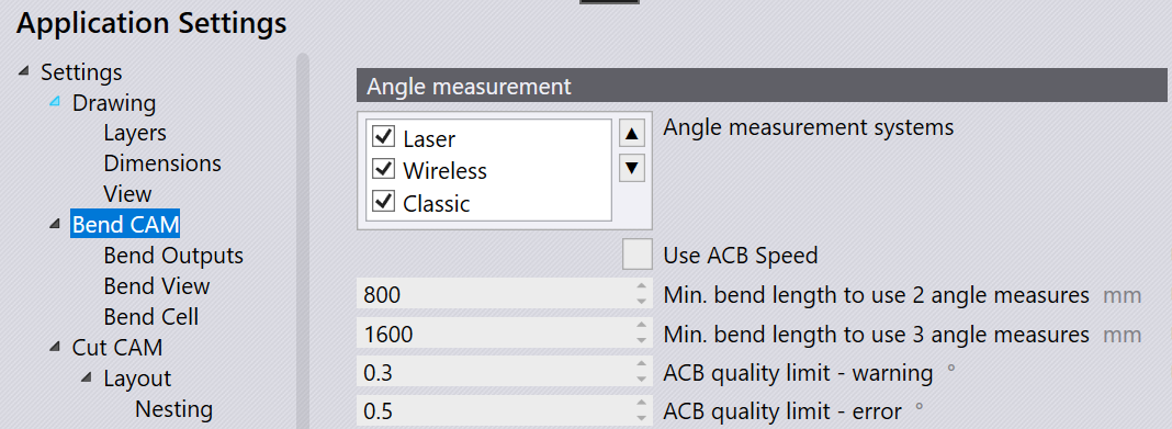
The Angle measurement section of the Settings/BendCAM page has a choices list that lets you turn on or off the various angle measurement systems. You can prioritize one over the other by selecting it and moving it up or down using the up/down arrow buttons alongside. In this particular example, both disk and laser based angle-measurement are enabled, and we prioritize laser first.[2]
The Use ACB Speed option decides if the ACB Speed strategy (available on Touchpoint machines) will be used by default.
ACB methods
There are different ACB Methods that are usable in Flux. Most of these are common between disk based and laser based angle measurement, so we discuss the different methods first.
Identify
The Identify or Identification or Identify Springback method is the canonical use of the ACB system. The press brake uses the angle-measurement system to measure the actual angle being formed when the part is bent. After the part is fully bent, the machine goes to the decompression state to allow the metal to spring back. The spring back is also measured using ACB, and is compensated for by a precise over-bending. To avoid the possibility of overshooting the target angle during measurement, the machine aims for a slight underbending at first, and then does a subsequent re-bending to reach the target. This is the most accurate, but also the most time-consuming ACB method.
Learn Y
In the Learn Y method, the ACB system is not used at all. The beam Y target (bottom dead center) is simply copied from an earlier bend (known as a Reference bend) that has already been measured using the Identify method. This earlier bend must be identical in terms of angle, radius and tool usage.
Learn SB
In the Learn SB or Learn Springback method, the ACB system uses the spring-back angle from a previous bend that has been measured using the Identify method. The ACB system is still used to regulate the bending, but since a second measurement after decompression is not required, the cycle is faster than a full Identify cycle.
Enter SB
The Enter SB, or Enter Springback or Corrected or ACB Smart method uses the ACB system to measure the target angle, but uses a spring-back value that is entered by the user. In other words, the ACB will simply bend the part to the target angle + the user-entered correction value. No second measurement is taken after decompression.
Symbols for ACB
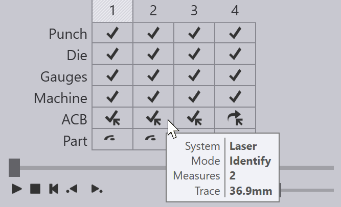
Flux uses several icons for representing various ACB methods or ACB errors and warnings. These are explained in bend navigator page.
These icons, along with other information about the ACB systems and methods being used, are all displayed on the ACB row of the bend navigator:
Notes about angle measurement
Laser system names
The laser based angle measurement system is known by different names like ACB-Laser or LCB. These are all programmed identically in Flux, though the actual hardware and machine implementation differ. Most of the Flux user interface just uses the word ACB or ACB-Laser, so we will use this term in this discussion as well.
Auto-tooler behavior
The Flux auto-tooler assigns ACB laser methods to each bend in an optimum manner. Initially, it starts with using the Identify method for the first bend, and then tries to use the Learn Y method for successive bends where possible. If there is already a bend with the same angle, radius, tool-set and with a similar grain orientation, Flux will use the Learn Y method, rather than doing another Identification.
Some bends may be skipped automatically because:
-
The bending angle is not within the measurement range of the sensor (too acute / too obtuse).
-
This is not an air-bending (for example, coining, Z-bending, hem or fold)
-
This is a pre-bend for another bend (does not need a precise angle)
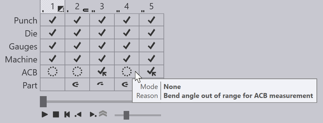
The image above shows a part where some bends have no ACB method - these are indicated with the hollow circle icons in the ACB row, and the tool-tip for each cell indicates a reason why no ACB measurement is performed.
Getting a valid measurement
When an ACB measurement is performed, Flux will decide whether one, two or three measurements are required based on the length of the bend line. The actual measurement positions are computed automatically, but can also be modified using the ACB panel.
Typically, Flux will move both the ACB sensors ganged, and will use both front and rear sensors for an ACB measurement, but this can also be edited.
Flux can evaluate the laser trace length for an ACB measurement. This is the length of the projected laser line that is visible to the camera. Parts of the line may be obstructed by the die, or by the gauges. Some parts may go over holes in the sheet, or over formings. The evaluation takes all these into account and can compute the actual length of line available to the optical system. Flux compares this available length against a machine-defined minimum and ideal length, and raises an appropriate error or warning (as shown in the Flux Symbols section above).
Flux has some intelligence to move the measurement position to the left or right to avoid holes, formings or other factors that can limit the trace length. In addition, Flux will also automatically add a retraction to the gauges if they come in the way of a laser measurement. In addition, the laser trace length evaluation is done continuously, so if you move the ACB sensor positions or adjust the gauges, you can see the results immediately in the navigator.