Flux Reference Manual

  • Welcome to Flux
  • Introduction
    • Installing the software
    • The user interface
    • Part workflow
  • CAD
    • 2-D Import
      • 2-D Cleanup
    • 3-D Import
      • Import 3D Model
      • Import assembly
      • Form detection
      • Component detection
    • Modifying the geometry
    • Attachments
  • Laser CAM
    • Part workflow
      • Editing panels
        • Laser cut
          • Approach
          • Withdrawal
          • Microjoint
          • Advanced
        • Contour
        • Scrap cut
        • Part
        • Corner treatment
      • Quick-Nest
    • Job workflow
      • Job panel
        • Sheets tab
        • Parts tab
        • Layouts tab
        • Summary tab
      • Edit layout
        • Nesting modes
        • Placement panel
        • Sequencing
        • Slice sheet
    • Bevel cut
      • Open contours
      • Variable bevel
      • Miscellaneous
    • Advanced
      • Finishing rules
      • Edit LTT
      • FlyLine
      • TwinLine
        • Strategy
        • Microjoints
        • Further settings
      • DetectLine
  • Bend CAM
    • Create bend data
    • Bend navigator
    • Edit bend data
      • Edit a bend
      • Edit a tool mount
      • Edit a bend setup
      • Edit the back-gauges
      • Edit angle measurement
      • Bends spreadsheet
      • Changing the sequence
      • Adding setups and stations
    • Advanced
      • Angle measurement
      • Batch process
      • Recompute solution
      • Tonnage check
    • Bending Aids
  • BendMaster CAM
    • Bend navigator
    • Part pickup
      • Pickup from pallet
      • Pickup from dispenser
    • Robotic bending
      • Insertion
      • Bending
      • Extraction
    • Regripping
      • Regrip panel
      • Add regrip
      • Edit regrip
      • Regrip with jaw
      • RG-Stations panel
    • Part deposit
      • Deposit panel
      • Repeat and sequence
      • Add separator sheets
      • Lock part-rest
      • Deposit pattern types
    • Advanced
      • Waypoints
      • Cell configuration
      • Custom Cell Components
      • Gripper database
        • Create a gripper
        • Import gripper from DXF
        • Import Suction Cup
  • FlexCell CAM
    • Bend navigator
    • Part pickup
      • Pickup from pallet
      • Centering table
    • Robotic bending
      • Insertion
      • Bending
      • Extraction
      • Advanced
    • Regripping
      • Regrip panel
      • Add/Remove regrip
      • Gripper Panel
      • RG-Stations panel
    • Part deposit
      • Deposit panel
      • Deposit Tabs
    • Advanced
      • Waypoints
      • Cell configuration
      • Gripper database
        • Create a gripper
        • Import gripper from DXF
    • Troubleshooting
  • Fold CAM
    • Create fold data
    • The Fold view
    • Editing Fold data
      • Edit a bend
      • Edit a side/section
      • Change the sequence
      • Edit the blank-holders
      • Edit the gauging
      • Edit the blades
      • Edit the loading
      • Edit the unloading
    • Tool inventory
    • Advanced
      • Custom air-gap tables
      • Manual bend completion
      • Required flange length
  • Settings
    • Drawing
      • Layers
      • Dimensions
      • View
    • Bend CAM
      • Machine defaults
      • Bend outputs
      • Bend view
      • Bend cell
    • Cut CAM
      • Layout
        • Nest settings
        • Sheet
        • Sheet handling
        • Skeleton cuts
        • Work support
      • Laser CAM
        • Sequence
      • Cut outputs
      • Cut view
    • Panel bending
      • Defaults
      • ZBW carriers
      • Outputs
    • Reports
      • Item defaults
    • Import/Export
    • Environment
  • Database
    • Materials
    • Machines
    • Bend tools
    • Bend deductions
    • Bend grippers
    • Forms and Components
  • Reports
    • Report designer
    • Fields, pictures and tables
    • Bands (sub-reports)
    • Labels, bitmaps and shapes
  • Appendix
    • Supported 3D formats
    • Separator sheet DXF
    • Bend tool DXF
    • The Adapt Geometry feature
BendMaster CAM
/
Advanced
/
Waypoints

Waypoints

Overview

Each movement of the BendMaster consists of waypoints which are passed one after the other. All waypoints of a movement are determined by Flux, but most of them can be adjusted. Points that are directly related to the tracking during the bending process cannot be changed. Various settings used to control the waypoints are listed below:

  1. Change the position of a waypoint

  2. Insert a new waypoint or remove an existing waypoint

  3. Adjust the motion properties such as speed and interpolation

  4. Add a new waypoint at desired position

To access the Waypoints panel:

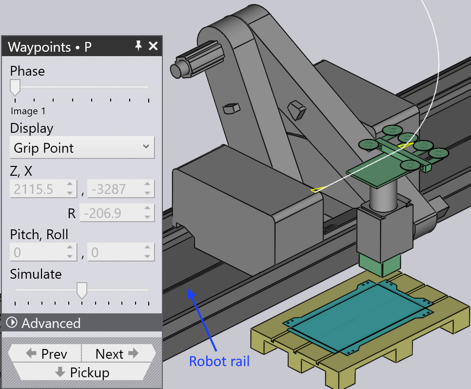
  • Click directly on the robot rail

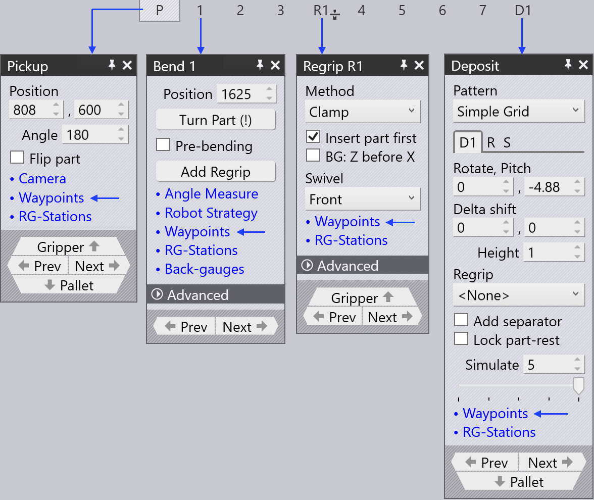
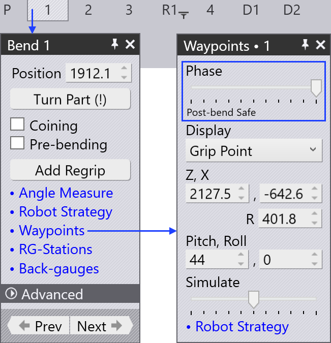
  • Click the Waypoints link from Pickup panel, Bend panel, Regrip panel or Deposit panel.

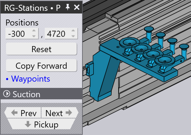
  • Click the waypoints link in any of the RG-Stations panel
Waypoints Panel
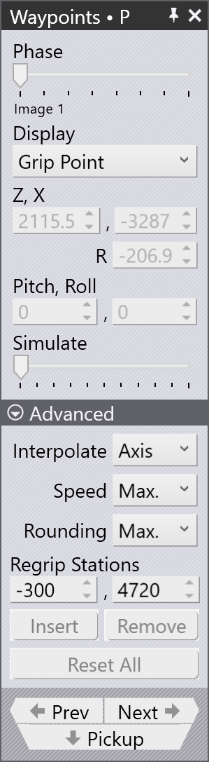
Figure 1. Waypoint panel
Bend navigator
Figure 2. Bend navigator panels
RG-station
Figure 3. RG-Stations panel

Waypoints panel

Waypoints

A typical waypoints panel is shown alongside:

  • The Phase slider shows the step by step movement of a waypoint. Each phase reflects a particular robot operation like pickup, bend, regrip and deposit.

  • Use the Display option to view the:

    • grip point

    • wrist point

    • robot axes.

  • The position and angle of the wrist or gripper are displayed and can be edited. If the robot axes is selected, the robot axes values are displayed and can be edited.

  • The yellow trace shows the path from the previous step to this one, and from this step to the next one (see image below). The 3 small triangles indicate the local X and Y coordinates of the robot (wrist or gripper).

  • The Simulate slider is used to move the simulation from the previous phase to the next phase. If this is in the middle, that is the actual phase we are editing.

  • The Interpolate setting is used to switch between linear and axis-oriented interpolations.

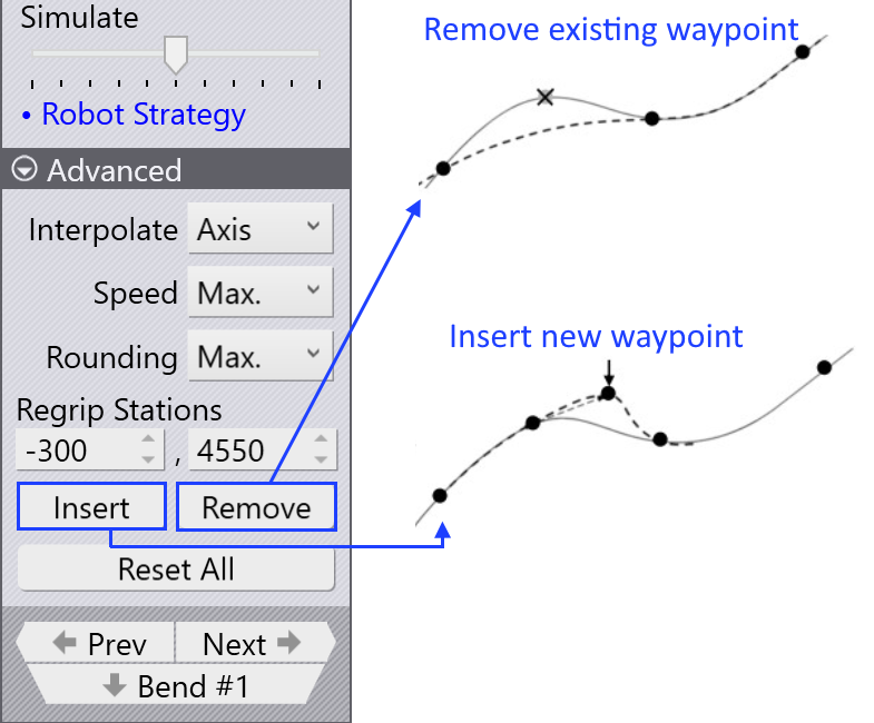
  • The Speed and Rounding settings are used to edit the speed and accuracy setting for this step.

  • Regrip stations field is used to change the position of regrip stations along its axis.

  • Insert option is used to create new waypoint by entering new values. Newly added waypoints can be removed by Remove option.

  • Use the Prev and Next buttons to go to the next or previous steps (or you can also use the Left and Right arrow keys). Clicking on Next button will show each step in a phase. At the end of the phase, next corresponding waypoint panel is displayed.

Properties of waypoints

Depending on the state of the process, each waypoint is given a set of attributes pertaining to the kind of interpolation, the speed, and the precision of movement. If required, these attributes can be changed.

These settings are controlled in the Advanced section of the waypoint panel.

Table 1. Interpolate
Interpolate type Description

Linear

Linear movement of the TCP along a path

Axis

The movement from the starting position to the end position is as quick as possible, regardless of the path.
No TCP linear movement.

Table 2. Speed
Speed type Description

Max.

Maximum speed

Fast

75% of the maximum speed

Medium

50% of the maximum speed

Reduced

30% of the maximum speed

Slow

20% of the maximum speed

Table 3. Rounding
Rounding type Description

Max.

Rounding starts at 50% of the shorter path length

Large

Rounding starts at 35% of the shorter path length

Medium

Rounding starts at 20% of the shorter path length

Reduced

Rounding starts at 10% of the shorter path length

Fine

Rounding starts at 5% of the shorter path length

Exact

The calibration point is approached exactly without overlaying

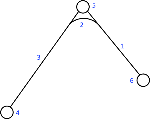
Waypoint path
  1. Path length between the waypoint point and the endpoint

  2. Executed length

  3. Path length between the start point and the waypoint

  4. Waypoint 3 (end point)

  5. Waypoint 2 (rounding point)

  6. Waypoint 1 (start point)

Display waypoints

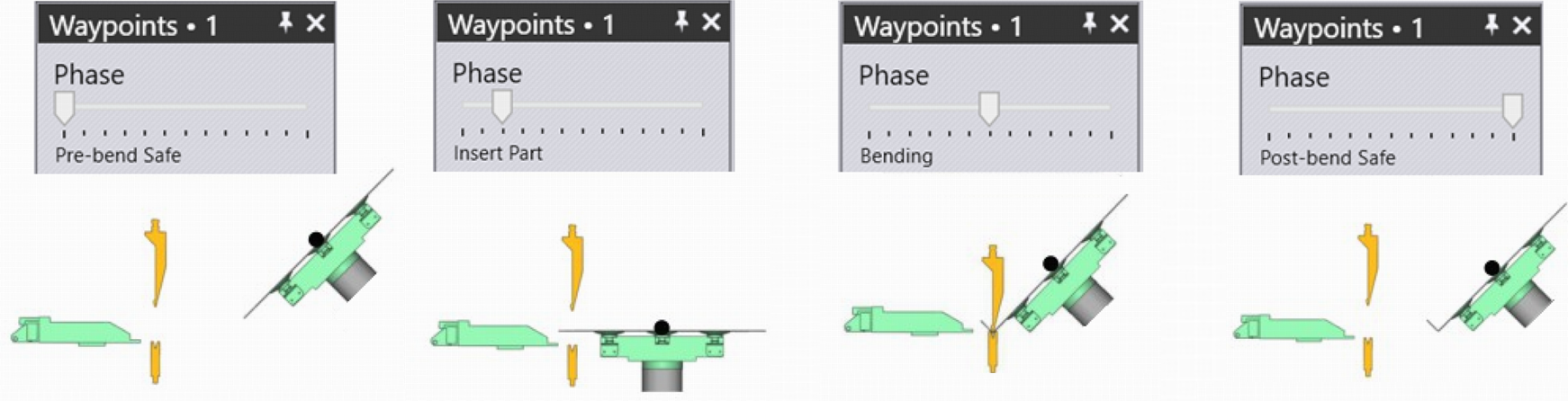
When a bend part is tooled, all the waypoints are automatically calculated for each movement phase. These points can be simulated phase by phase with a corresponding description.
Waypoints phase

Below images shows the waypoint phases of first bending operation (in side view):
Waypoints phase

Modify waypoints

A waypoint’s location can be changed if needed, for example, to prevent going over the axis.

Among other aspects pertaining to collision avoidance, unwanted waypoints can be eliminated or new waypoints can be added.

  • When an existing waypoint position is changed, Flux shows a warning message. Click OK to proceed with changing the waypoint.
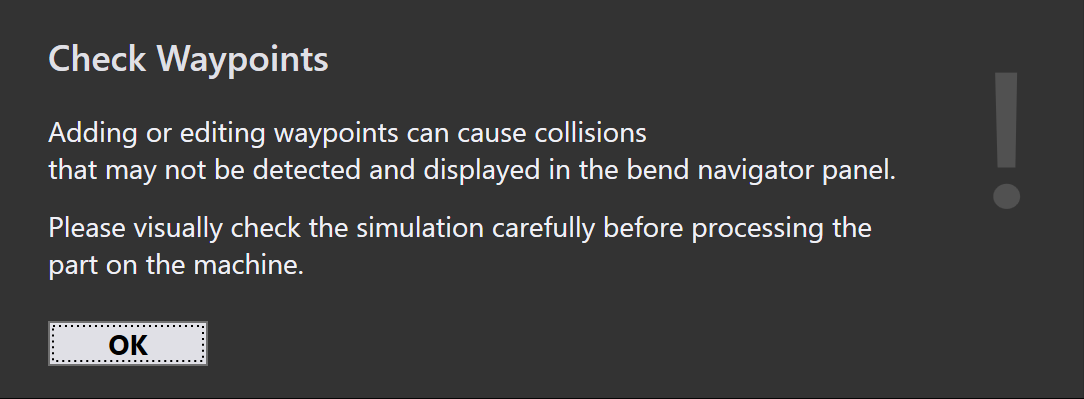
    Waypoint caution
  • Clicking the Insert button will add new waypoints.
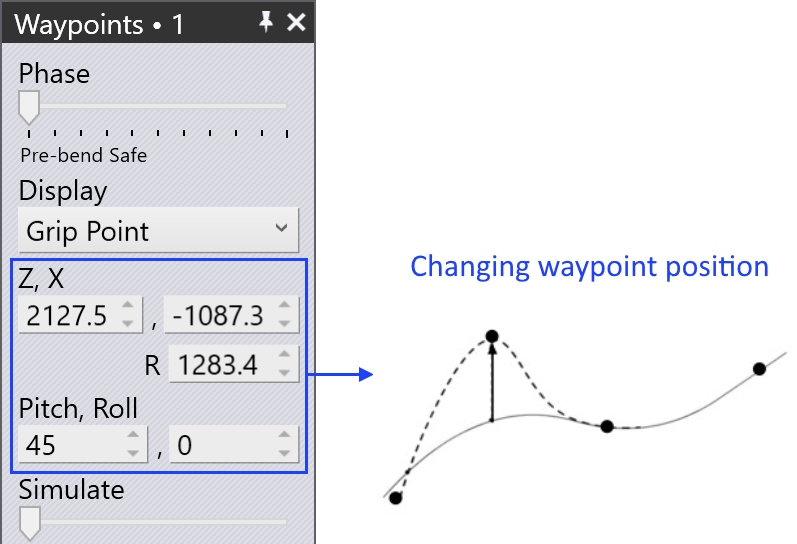
    Change waypoint Add remove waypoint

  • Newly added waypoints are denoted by +1,+2,ect., in the phase name as shown below:
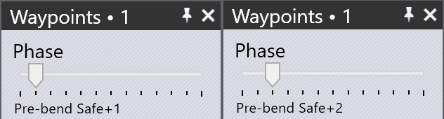
    Modify waypoints

Simulate waypoints

By default the simulate slider is in the middle position. Movement of the robot from one waypoint to the other is seamlessly simulated using this slider.
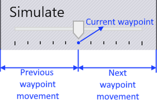
Simulate

Contents

  • Overview
  • Properties of waypoints
  • Display waypoints
  • Modify waypoints
  • Simulate waypoints
Advanced Cell configuration

      Copyright © 2025 TRUMPF Metamation. All rights reserved.

    Compiled by Bento