
Flux Reference Manual

  • Welcome to Flux
  • Introduction
    • Installing the software
    • The user interface
    • Part workflow
  • CAD
    • 2-D Import
      • 2-D Cleanup
    • 3-D Import
      • Import 3D Model
      • Import assembly
      • Form detection
      • Component detection
    • Modifying the geometry
    • Attachments
  • Laser CAM
    • Part workflow
      • Editing panels
        • Laser cut
          • Approach
          • Withdrawal
          • Microjoint
          • Advanced
        • Contour
        • Scrap cut
        • Part
        • Corner treatment
      • Quick-Nest
    • Job workflow
      • Job panel
        • Sheets tab
        • Parts tab
        • Layouts tab
        • Summary tab
      • Edit layout
        • Nesting modes
        • Placement panel
        • Sequencing
        • Slice sheet
    • Bevel cut
      • Open contours
      • Variable bevel
      • Miscellaneous
    • Advanced
      • Finishing rules
      • Edit LTT
      • FlyLine
      • TwinLine
        • Strategy
        • Microjoints
        • Further settings
      • DetectLine
  • Bend CAM
    • Create bend data
    • Bend navigator
    • Edit bend data
      • Edit a bend
      • Edit a tool mount
      • Edit a bend setup
      • Edit the back-gauges
      • Edit angle measurement
      • Bends spreadsheet
      • Changing the sequence
      • Adding setups and stations
    • Advanced
      • Angle measurement
      • Batch process
      • Recompute solution
      • Tonnage check
    • Bending Aids
  • BendMaster CAM
    • Bend navigator
    • Part pickup
      • Pickup from pallet
      • Pickup from dispenser
    • Robotic bending
      • Insertion
      • Bending
      • Extraction
    • Regripping
      • Regrip panel
      • Add regrip
      • Edit regrip
      • Regrip with jaw
      • RG-Stations panel
    • Part deposit
      • Deposit panel
      • Repeat and sequence
      • Add separator sheets
      • Lock part-rest
      • Deposit pattern types
    • Advanced
      • Waypoints
      • Cell configuration
      • Custom Cell Components
      • Gripper database
        • Create a gripper
        • Import gripper from DXF
        • Import Suction Cup
  • FlexCell CAM
    • Bend navigator
    • Part pickup
      • Pickup from pallet
      • Centering table
    • Robotic bending
      • Insertion
      • Bending
      • Extraction
      • Advanced
    • Regripping
      • Regrip panel
      • Add/Remove regrip
      • Gripper Panel
      • RG-Stations panel
    • Part deposit
      • Deposit panel
      • Deposit Tabs
    • Advanced
      • Waypoints
      • Cell configuration
      • Gripper database
        • Create a gripper
        • Import gripper from DXF
    • Troubleshooting
  • Fold CAM
    • Create fold data
    • The Fold view
    • Editing Fold data
      • Edit a bend
      • Edit a side/section
      • Change the sequence
      • Edit the blank-holders
      • Edit the gauging
      • Edit the blades
      • Edit the loading
      • Edit the unloading
    • Tool inventory
    • Advanced
      • Custom air-gap tables
      • Manual bend completion
      • Required flange length
  • Settings
    • Drawing
      • Layers
      • Dimensions
      • View
    • Bend CAM
      • Machine defaults
      • Bend outputs
      • Bend view
      • Bend cell
    • Cut CAM
      • Layout
        • Nest settings
        • Sheet
        • Sheet handling
        • Skeleton cuts
        • Work support
      • Laser CAM
        • Sequence
      • Cut outputs
      • Cut view
    • Panel bending
      • Defaults
      • ZBW carriers
      • Outputs
    • Reports
      • Item defaults
    • Import/Export
    • Environment
  • Database
    • Materials
    • Machines
    • Bend tools
    • Bend deductions
    • Bend grippers
    • Forms and Components
  • Reports
    • Report designer
    • Fields, pictures and tables
    • Bands (sub-reports)
    • Labels, bitmaps and shapes
  • Appendix
    • Supported 3D formats
    • Separator sheet DXF
    • Bend tool DXF
    • The Adapt Geometry feature
Laser CAM
/
Part workflow

Part workflow

You can create Cut Technology Data for a sheet-metal part using the Cut module. Let us assume you have already installed a machine, and that you have imported a CAD part (2D or 3D), cleaned it up to get a usable sheet metal part. You can click on the material name and the sheet thickness in the document tab at the bottom to edit those, as explained in the 2D-Cleanup page.
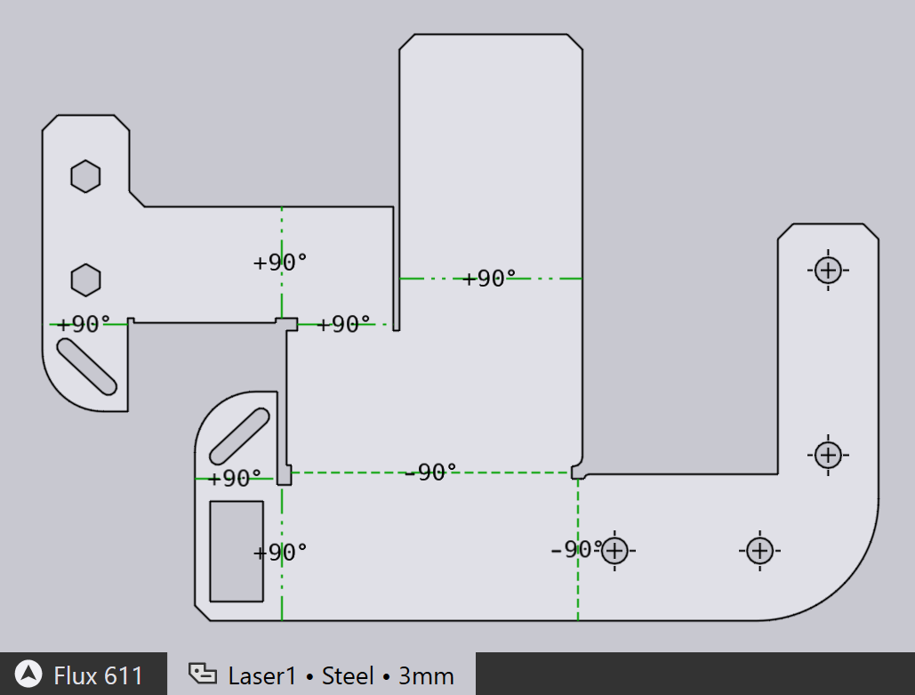
2D Part

Switching to Cut CAM

Now, the part can be tooled up for laser cutting by just pressing the L key. The part is tooled up with the default laser machine, which is the laser machine that was most recently used. The cutting paths, approach segments, corner processing and tooling sequence are all set up and you should see a result like this:
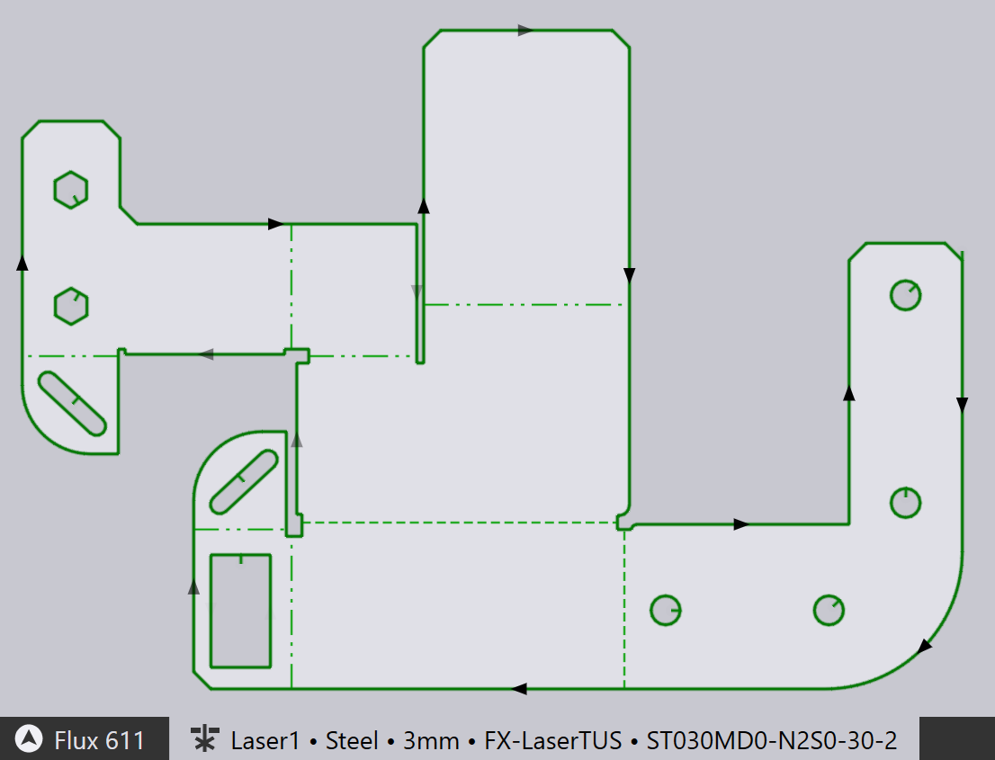
Tooled-up Part

The tab at the bottom shows that the part has been tooled up for the FX-LaserTUS machine, and uses the LTT (laser technology table) ST030MD0-N2S0-30-2.

  • You can tool up the part for a different machine by clicking on the machine name and selecting a new machine.

  • You can select a different LTT from among the ones available for the selected machine, material and thickness by clicking on the LTT name and selecting a different one:

    Select LTT

See also the the Workflow panel, which can be accessed by pressing the W key. This provides more control over creating cut technology data, and also options for routing the part through bending, and nesting.

Sequence navigator

The auto-tooler also computes a sequence in which the laser cuts for the part should be processed. This same intra-part sequence can also be used when the part is inserted into a layout along with other parts. You can see the traverse lines between the cuts by toggling the Traverse setting in the toolbar on the left (or by using the X key).
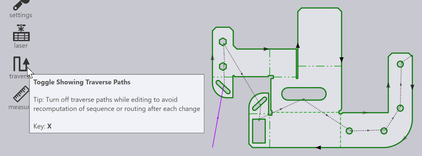
Show Traverse Lines
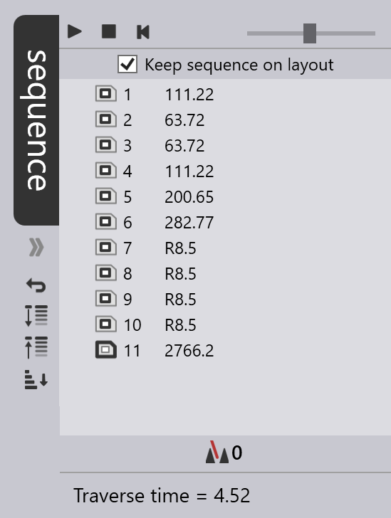
Sequence Navigator

You can also edit the sequence by opening the Sequence navigator along the right edge of the window, by clicking on the chevron beneath the tab, or by pressing the Z key.

Each tooling item in the part has one entry in the sequence navigator, and you can re-order the tooling by moving these items around using drag-and-drop. You can also do some other operations here, such as controlling whether the head is raised before traversing to the next contour, etc.

The sequence navigator is discussed in more detail in the Layout Sequencing page, where we use the navigator to view and edit the sequence for an entire layout (sheet with multiple parts).

Contents

  • Switching to Cut CAM
  • Sequence navigator
Laser CAM Editing panels

      Copyright © 2025 TRUMPF Metamation. All rights reserved.

    Compiled by Bento