Flux Reference Manual

  • Welcome to Flux
  • Introduction
    • Installing the software
    • The user interface
    • Part workflow
  • CAD
    • 2-D Import
      • 2-D Cleanup
    • 3-D Import
      • Import 3D Model
      • Import assembly
      • Form detection
      • Component detection
    • Modifying the geometry
    • Attachments
  • Laser CAM
    • Part workflow
      • Editing panels
        • Laser cut
          • Approach
          • Withdrawal
          • Microjoint
          • Advanced
        • Contour
        • Scrap cut
        • Part
        • Corner treatment
      • Quick-Nest
    • Job workflow
      • Job panel
        • Sheets tab
        • Parts tab
        • Layouts tab
        • Summary tab
      • Edit layout
        • Nesting modes
        • Placement panel
        • Sequencing
        • Slice sheet
    • Bevel cut
      • Open contours
      • Variable bevel
      • Miscellaneous
    • Advanced
      • Finishing rules
      • Edit LTT
      • FlyLine
      • TwinLine
        • Strategy
        • Microjoints
        • Further settings
      • DetectLine
  • Bend CAM
    • Create bend data
    • Bend navigator
    • Edit bend data
      • Edit a bend
      • Edit a tool mount
      • Edit a bend setup
      • Edit the back-gauges
      • Edit angle measurement
      • Bends spreadsheet
      • Changing the sequence
      • Adding setups and stations
    • Advanced
      • Angle measurement
      • Batch process
      • Recompute solution
      • Tonnage check
    • Bending Aids
  • BendMaster CAM
    • Bend navigator
    • Part pickup
      • Pickup from pallet
      • Pickup from dispenser
    • Robotic bending
      • Insertion
      • Bending
      • Extraction
    • Regripping
      • Regrip panel
      • Add regrip
      • Edit regrip
      • Regrip with jaw
      • RG-Stations panel
    • Part deposit
      • Deposit panel
      • Repeat and sequence
      • Add separator sheets
      • Lock part-rest
      • Deposit pattern types
    • Advanced
      • Waypoints
      • Cell configuration
      • Custom Cell Components
      • Gripper database
        • Create a gripper
        • Import gripper from DXF
        • Import Suction Cup
  • FlexCell CAM
    • Bend navigator
    • Part pickup
      • Pickup from pallet
      • Centering table
    • Robotic bending
      • Insertion
      • Bending
      • Extraction
      • Advanced
    • Regripping
      • Regrip panel
      • Add/Remove regrip
      • Gripper Panel
      • RG-Stations panel
    • Part deposit
      • Deposit panel
      • Deposit Tabs
    • Advanced
      • Waypoints
      • Cell configuration
      • Gripper database
        • Create a gripper
        • Import gripper from DXF
    • Troubleshooting
  • Fold CAM
    • Create fold data
    • The Fold view
    • Editing Fold data
      • Edit a bend
      • Edit a side/section
      • Change the sequence
      • Edit the blank-holders
      • Edit the gauging
      • Edit the blades
      • Edit the loading
      • Edit the unloading
    • Tool inventory
    • Advanced
      • Custom air-gap tables
      • Manual bend completion
      • Required flange length
  • Settings
    • Drawing
      • Layers
      • Dimensions
      • View
    • Bend CAM
      • Machine defaults
      • Bend outputs
      • Bend view
      • Bend cell
    • Cut CAM
      • Layout
        • Nest settings
        • Sheet
        • Sheet handling
        • Skeleton cuts
        • Work support
      • Laser CAM
        • Sequence
      • Cut outputs
      • Cut view
    • Panel bending
      • Defaults
      • ZBW carriers
      • Outputs
    • Reports
      • Item defaults
    • Import/Export
    • Environment
  • Database
    • Materials
    • Machines
    • Bend tools
    • Bend deductions
    • Bend grippers
    • Forms and Components
  • Reports
    • Report designer
    • Fields, pictures and tables
    • Bands (sub-reports)
    • Labels, bitmaps and shapes
  • Appendix
    • Supported 3D formats
    • Separator sheet DXF
    • Bend tool DXF
    • The Adapt Geometry feature
Fold CAM
/
Editing Fold data
/
Edit the blades

Edit the blades

Blade panel

The blade settings for each bend can edited by accessing the Blade panel. To access the blade panel for a particular bend:

  • Switch to that bend by clicking on the number in the fold navigator, or by using PageUp or PageDn keys.

  • Click on the standard blade, the ZBW blade or the ZBW blade carrier to open the Blade panel.
Edit-Blade

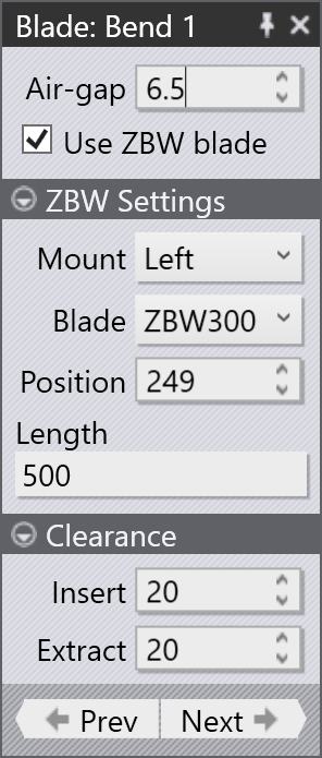
The blade panel is displayed as shown alongside. Here are the various settings you can control from this panel:

  • Use the Air-gap setting to adjust the air-gap. As the air-gap is adjusted from its default value, the fold navigator will display a non-standard air-gap warning. Collision checking will also be done immediately with the updated air-gap and you can tune the air-gap to prevent collisions. The bending force will also be computed, and if you set the air-gap so low that the maximum bending force is exceeded, the fold navigator will display this as an error.

  • The Use ZBW blade checkbox can be used to turn on or off the use of ZBW blades for this bend. If the bend is too long, or no ZBW blades are available, this may be grayed out (moving the mouse over the check-box will tell you why it is grayed out).

ZBW settings

  • Click on the ZBW Settings header to open that section, if it is closed.

  • Use the Mount list to select if this bend should use a blade mounted on the Left carrier, or the Right carrier. For bends that contain multiple segments, you can also choose Both, to indicate that some segments are processed with the left blade while others are processed with the right blade.

  • Use the Blade selector to pick one of the ZBW blades available for this machine.

  • Use the Position selector to change the position of the blade along the machine’s bending axis. For both blades, this position indicates the location of the reference edge of the blade (the edge closer to the back-gauge) along the machine’s bending axis, with 0 being at the center. As you adjust this position, you can see the ZBW blade immediately move, and the navigator at the top displays the current status. These are the possible status indicators.[1]

    • It is possible the blade is slightly short of the bend span (5 to 10 mm short). This is indicated as a warning.

    • It is possible the blade is more than 10 mm short of the bending span (the bend overhangs the blade by more than 10 mm on one side or the other). This is indicated as an error.

    • It is possible the blade collides with the part during the bending cycle; this is indicated as an error.

  • Use the Length input to enter the length of the blade. It is possible to create a blade mount that has multiple spans, separated by gaps.

Clearance

  • Click on the Clearance header to open that section, if it is closed.

  • Use the Insert clearance value to adjust the clearance between the ZBW blade and the part as the blade is inserted.

  • Use the Extract clearance value to adjust the clearance between the ZBW blade and the part while the blade is extracted (or moved to a different position for the next bend).

Mount lengths and gaps
Mount length

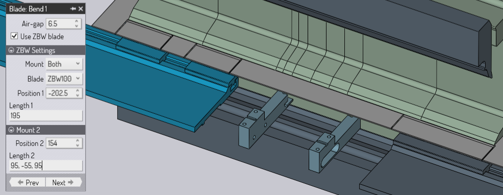
The image above shows Both mounts being used. There is now an additional section that allows you to enter the position and length of the second mount. The Length 2 setting has been set to 95,-55,95. This means that there is a 95 mm section of blade, a 55 mm gap, and an additional 95 mm section of blade. Positive numbers are used to indicate blade lengths, while negative numbers indicate gaps between blade segments. The measurements always start from the reference edge of the blade carrier (the edge closest to the back-gauges).

Using this length input, it is possible to compose a blade with any number of segments, separated by gaps. Note that the blade segment lengths are limited to being multiples of 5 mm, while the gaps can be set at any value.

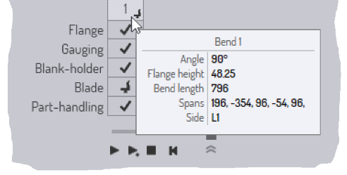
The same notation (of using positive number for spans, with negative numbers for gaps) is also seen in the tool-tip that is displayed for such a multi-segment bend.
Blade Tooltip
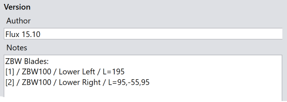
The notation is also used to express the blade length in the NC program that is generated. The Notes section of the NC program shows this blade composition thus:
Blade NC

1. As you adjust the blade position and length, these errors or warnings are immediately computed and updated, so it is quite simple to adjust these until the blade length and position are perfect.

Contents

  • Blade panel
  • ZBW settings
  • Clearance
  • Mount lengths and gaps
Edit the gauging Edit the loading

      Copyright © 2025 TRUMPF Metamation. All rights reserved.

    Compiled by Bento