
Recompute solution
When you press B, or use the workflow panel to compute a solution,
Flux calculates a bend solution using a set of default settings and
parameters. You can do a re-calculation of this solution using different
settings by clicking on the Recompute  menu from the command bar. Sometimes, this is also useful to complete the
computation after you have interactively edited some tooling, or the sequence.
menu from the command bar. Sometimes, this is also useful to complete the
computation after you have interactively edited some tooling, or the sequence.
For example:
-
You can change the sequence, and ask Flux to compute new tooling stations while keeping the sequence unchanged.
-
You could change the tooling stations, and ask Flux to compute a new sequence, or to align the part to the newly created stations.
-
You can try the tooling operation with a different set of tools, or try using an already-created Setup.
The Recompute dialog
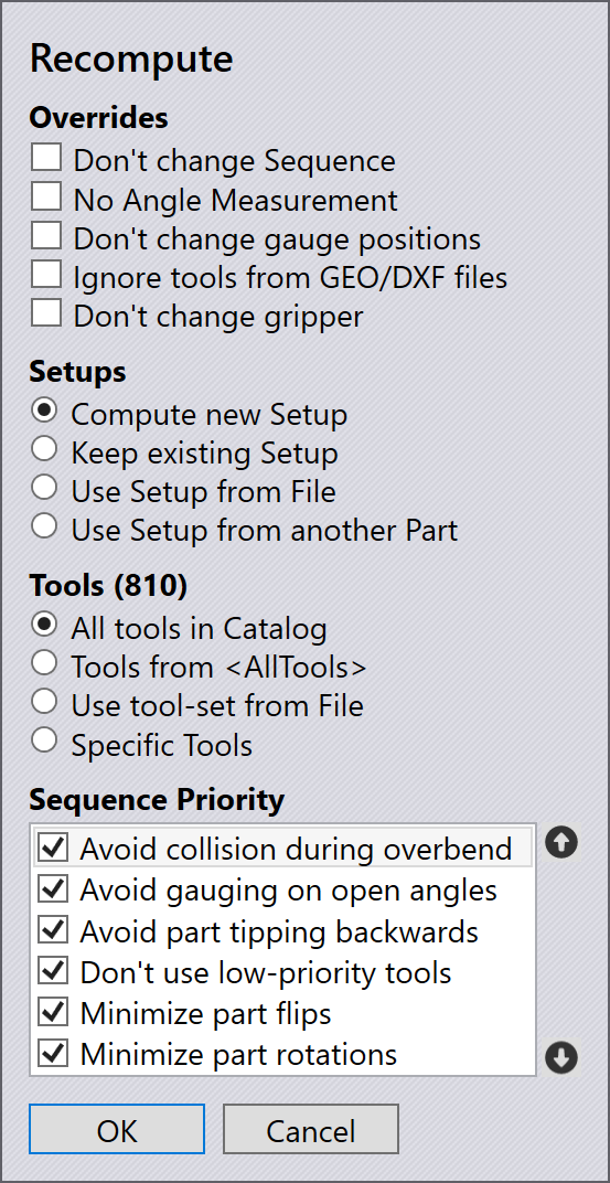
The Recompute dialog looks like the image alongside.
Overrides
This section contains some switches you can use to over-ride the default behavior of Flux.
-
Turn on the Don’t change sequence switch to force Flux to compute a new solution without changing the sequence. Different tooling stations, gauging positions or part insertion directions will be tried by Flux, while holding the sequence unchanged.
-
If the No angle measurement switch is turned on, Flux computes a solution that performs no angle measurements, and will not use any gauging sensors (ACB tools).
-
The Ignore tools from GEO/DXF files tells Flux to ignore the tooling hints that are often found in GEO files, and sometimes in DXF file.
Setups
This section sets the strategy for tooling setups; by default, Flux will compute the Setup from scratch, but you can use these settings to change this behavior.
-
Compute new Setup is the default behavior - Flux will compute a setup using all the tools it is allowed to (see the Tools section below).
-
Keep existing Setup tells Flux that no Setup changes should be made; it tries to process all the bends using the current setup for the part. If some bends have collisions, or have insufficient tool length for processing, those errors remain uncorrected, and can be viewed after the recompute process.
-
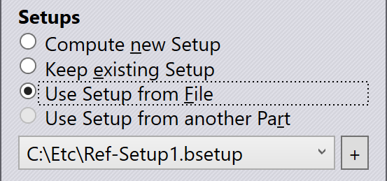
If you select Use Setup from File, you are prompted to pick a bend setup file (bsetup). The Setup loaded from this file is then used for computation; that setup is not modified, nor are any additional stations created. Setups you have recently loaded from file are displayed in the selector that appears below this section, and you can then click the + button near that selector to pick a different setup file.
-
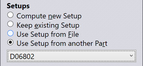
The Use Setup from another Part option is available only if there are some other parts currently open, and they have been tooled up for the same press brake. In this case, you can ask Flux to use the same setup as one of these other parts; a selector appears to let you choose the part you want.
Tools
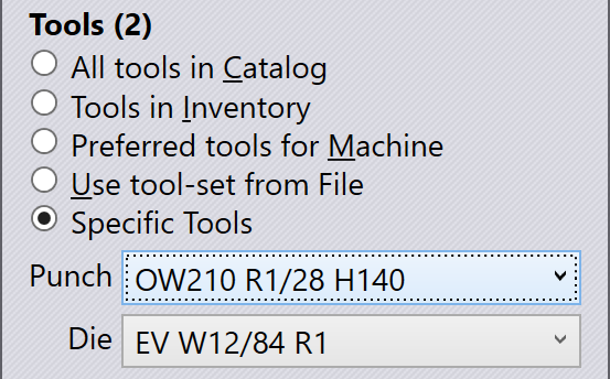
If you choose the Compute new Setup option in the section above, you can use the Tools section to pick the list of bend-tools that may be used to compute the new setup. If you choose one of the other options for the Setup, this section is not available.
-
Preferred tools for Machine is the default option. For each press brake, you can choose a set of tools[1] as the preferred tools, and Flux will use those tools when tooling up the part.[2] (If you have not actually set up the preferred tools for a machine, Flux uses all the tools in the inventory as the preferred tool-set for the machine).
-
If you choose Tools in Inventory, Flux will use all the tools that are available in the installation’s inventory. If you have not actually set up the inventory of tools, Flux uses all the tools in the Catalog as your inventory.
-
The All Tools in Catalog is the broadest selection of tools; Flux will use every tool available in the manufacturer’s tool catalog to attempting a solution. While this may mean the solution may not be actually feasible for production (using the inventory you have available), it is useful for a speculative exploration of what tools would be required to produce a particularly complex part. (In addition, this mode also tells Flux to assume an infinite inventory of pieces - that is, the optimum tooling is produced assuming you have an infinite number of pieces of each length).
-
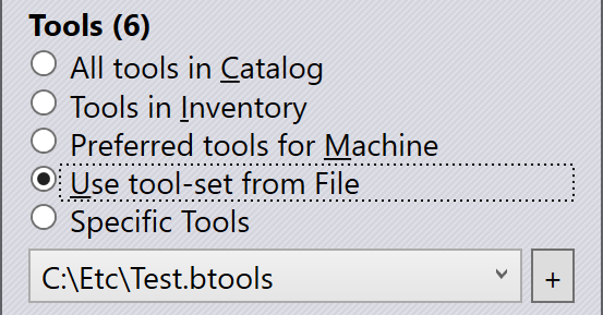
You can create custom tool-sets and store them in tool-list files (btools). These files can then be used to tool up the part, when you select the Use tool-set from File option. When you pick this option, you are prompted for a tool-list file, and tool-list files you have used recently are displayed for easy selection. You can click on the + sign near this list to pick a new tool list.
-
For the most direct control over the punches and dies, you can select the Specific Tools option, and then pick the exact punch and die you want to use.
Sequence priority
When sequencing the bends in a part, there are a few potentially conflicting requirements. For example, should Flux try to minimize the number of part rotations, or should it try to minimize the bends where the part’s center-of-gravity lies inside the machine? + It is quite likely that each operator may have a different set of priority rules, and also possible that different parts may require different priority settings. Flux therefore allows you to do a recomputation with a different ordering of priorities, using the Sequence priority section of this dialog.
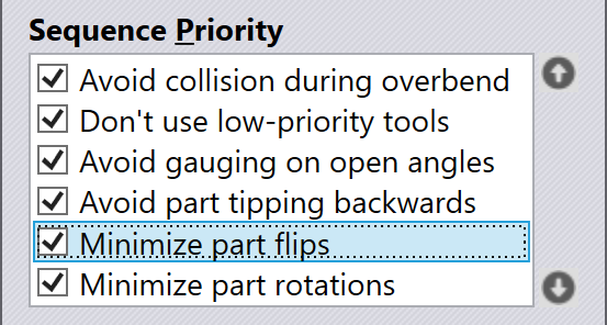
Use the  and
and  arrow
buttons on the right to shuffle the rules; items near the top are higher in
priority. You can turn some of these priority items off completely; this tells
Flux not to consider this as a factor when deciding the sequence.
(Sometimes, turning off some of these can yield a sequence that uses few tool
stations).
arrow
buttons on the right to shuffle the rules; items near the top are higher in
priority. You can turn some of these priority items off completely; this tells
Flux not to consider this as a factor when deciding the sequence.
(Sometimes, turning off some of these can yield a sequence that uses few tool
stations).
-
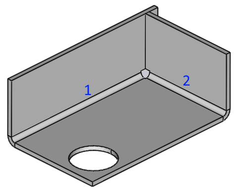
Avoid collisions during overbend: To achieve angle accuracy, most bends will need to be overbent slightly to compensate for springback. This sequence rule tells Flux to do bends in such an order that overbending is possible. For example, in the part below, we should do the bend 1 first and bend 2 next; the other order would block overbending.
-
Don’t use low-priority tools: Tells Flux to avoid using low-priority tools, or tools that are not in the preferred list, as far as possible.
-
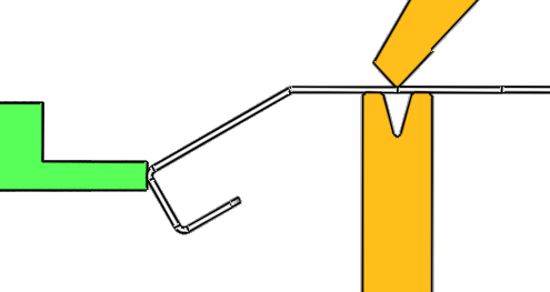
Avoid gauging on open angles: Gauging positions should ideally be in the same plane as the bend axis, and there should not be any already-processed bends between the bend line and the gauging point. Here is an example of a poor gauging that this rule tries to avoid:
-
Avoid part tipping backwards: Especially with heavy parts, it is useful to avoid situations where the center-of-gravity of the part lies behind the tool line. This rule tries to minimize such situations.[3]
-
Minimize part flips: Part flips are when the part has to be overturned (successive bends are in different up/down directions).
-
Minimize part rotations: A part rotation is when a part is turned left or right in the horizontal plane; this is considered to be easier for the operator than a part flip; the default ordering of these last two rules tries to favor part rotations over part flips, where possible.