
The Fold view
When you switch to the Fold CAM mode, the workspace displays the folding view. This shows a 3D image of the panel bender with the workpiece. This is how it would look for the TBC-5030 machine.
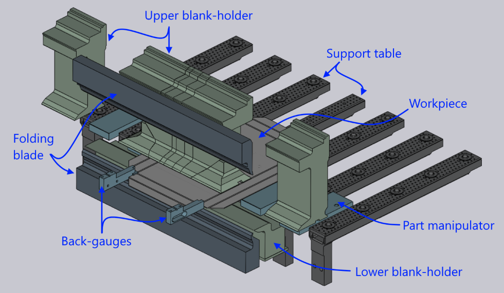
The panel bender is a large machine with a table that is typically longer than 3 meters. Displaying the entire machine would dwarf the workpiece and make it difficult to visualize the bending process. Thus, the bending view displays an abbreviated view of the machine. Various elements like the folding blades and lower blank holders are displayed only to the lengths required to cover the region of interest. Only the pieces of the upper blank-holders that are actually used for processing are displayed. Only some spars of the support table and some of the part manipulators are displayed. This abbreviated view makes it easier to follow the actual processing.
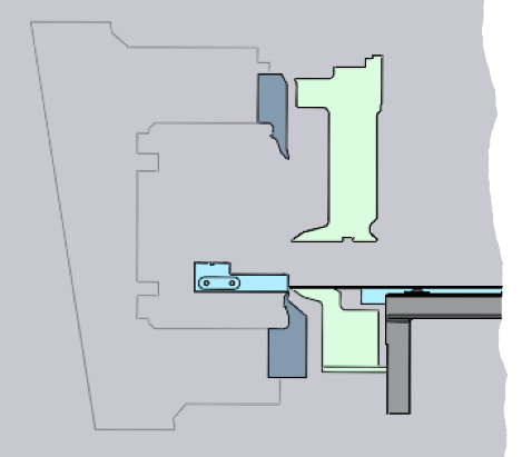
The C-Frame on which the blades are mounted is not usually displayed in the 3D view, since it would obstruct most of the view of the folding operations. However, when you rotate the 3D view to align it to an end-on orientation, the C-Frame is displayed as an outline (see image alongside). This makes it easy to see how the part geometry fits in relation with the C-Frame. When you rotate the 3D view into a different orientation, the C-frame is hidden.
The Fold navigator
When you are in the folding view, the Fold Navigator panel appears along the top edge of the Flux window. This navigator provides a quick way to navigate through various bend operations, and also an instant view into various status-checks for every bend. It provides controls to view or stop the folding simulation. Here is an example of how the fold navigator looks:
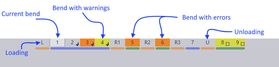
The navigator displays different colors for bends that have some warnings or errors. The current bend is displayed with an outlined box, and the thick dark lines between some bends represent side boundaries (where the operator has to rotate the part around to continue processing).
Simulation controls
When you move the mouse near the fold navigator, simulation controls appear.

-
The slider can be used to move the current bend through various phases of the folding operation (feed part to bending position, clamp with blank-holder, move folding blade, etc). As the slider is moved, the tool-tip displays the current phase of folding, and various parts of the machine move in the simulation. If there are any collisions, those parts are colored red to clearly highlight the collision.
-
The play controls near the left can be used to start the simulation, stop it, or rewind to the beginning. (Tip: You can also press Space to start or stop playing the fold simulation).
-
The play one button can be used to play just one bend; use this repeatedly to view the simulation of all the bends. (Tip: you can press Ctrl+Space to play just one bend).
-
The downward facing chevron near the middle can be used to expand the fold navigator, displaying more detailed information about the errors and warnings for various bends. (Tip: you can also press Z to expand/collapse the fold navigator display).
Fold navigator: expanded view
When you open the fold navigator by clicking the open button, or by pressing the Z key, this is how it looks:

For each bend, the navigator now displays a set of status icons. Each colored icon represents an error or a warning. Moving the mouse over the colored cell displays some more information about what the error or warning is (as you can see in the picture above).
Clicking on a cell that displays an error positions the simulation so that the error is immediately obvious. For example, clicking on a cell that displays a blade-crash error moves the simulation to the stage of the simulation where the blade crashes with the workpiece.
Status icons
There are several different status icons displayed in different rows of the Fold Navigator. The sections below explain the meanings of these icons. Note that you can always get more information about what an icon means by just moving the mouse over the icon.
The Flange row
The Flange row of the fold navigator displays information about intra-part collisions (one flange of the model colliding with another). Flux will try to avoid this where possible by altering the sequence. These are the icons you may see in the Flange row:
Icon |
Meaning |
|
No error, status OK |
|
A flange-flange collision happens during the bending |
|
This bend has been skipped (no processing for this bend) |


The Gauging row
The Gauging row of the fold navigator displays the gauging status. Since gauging is only used for the first bend in a side, all the other bends in a side will display a hollow circle icon (indicating that this bend requires no gauging operation).
Icon |
Meaning |
|
No error, gauging correctly computed |
|
Error: The back-gauge collides with the part during gauging |
|
Error: Gauging could not be computed for this side |
|
Information: This is not the first bend in this side; it does not require gauging |


The Blank-holder row
This row of the fold navigator displays status information about the blank-holder. These are the possible errors or warning icons you may see in this column. Some icons are used both for errors or warnings, and the distinction between the two is made based on the background color of the cell (yellow for warnings, orange-red for errors).
Icon |
Meaning |
|
No error - blank holder is correctly computed, and has no collisions |
|
Error: The part collides with the blank-holder |
|
Error: The blank-holder span is too short (there is more
than about 10 mm of overhang of the bend-line beyond the blank-holder). |
|
Information: This bend uses an ENW tool (moving the mouse over the cell provides more details) |


The Blade row
This row provide information about the folding blade used for this bend. The list below shows the possible icons you may see in this column:
Icon |
Meaning |
|
No error - the folding blade is correctly computed, and has no collisions |
|
Error: The part collides with the folding blade |
|
Error: The blade length span is too short
(there is more than about 10 mm of overhang of the bend-line beyond the blade).
This happens only when using a ZBW blade. |
|
Warning: A non-standard air-gap is being used to avoid a blade collision |
|
Error: ZBW carrier overtravel beyond axis limits |
|
Error: Overload - the required bending force is too high (the air-gap may need to be increased) |


The Part-handling row
This row displays information about the status of part-handling using the vacuum grippers or magnetic grippers. These are the icons that could be displayed here:
Icon |
Meaning |
|
No problems noted with the part handling |
|
Error: The part collides with the support table (for example, there is a downward flange that would protrude down into the support table) |
|
Information: The part is gripped with the front-face of the gripper |
|
Information: The part is gripped with the bottom-face of the gripper |
|
Warning: The gripper may have only a marginal overlap with the part |
|
Error: No gripping could be computed - there was no surface of the part that was suitable to position the gripper on |
|
Warning: The part needs to be flipped over by the operator at the start of this side |
|
The part needs to be manually extracted at the end of this side (the automatic extraction by the gripper is not possible because of the part fouling with the blank-holder) |


As you make changes in the blank-holder, blades, gripper or back-gauge configurations, the fold navigator is immediately updated with the new status. This immediate feedback makes it very easy to experiment with different configurations without having to issue a recompute command each time.