
Laser CAM
Cutting
There are three condition based on which a sheet is cut.
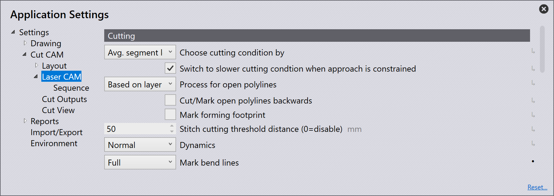
Choose cutting condition by - This setting is to define how the cutting condition will be selected. The options include Maximum segment length, Average segment length and Area.
Maximum segment length - The longest segment is used as threshold.
Average segment length - The average length for all segments is calculated and used as a threshold. Default setting in Flux.
Area - The area enclosed by the contour is used as threshold.
Switch to slower cutting condition when approach is constrained - The laser head switches to a slow speed cutting situation when the sheet geometry for the approach is complex.
Process for open polylines - When open polylines are found in a part, depending on which option is selected, Cut will process the polyline accordingly. The options includes Cut, Mark, None, and Based on layer.
None - The laser will ignore this line on the part drawing.
Mark - The laser will just mark this line, i.e. draw a visible line on the sheet metal that does not pierce through.
Cut - Flux will choose the appropriate laser condition for this polyline and the laser will cut it accordingly.
| For this setting to take effect, tooling must be recomputed changes to manual tooling will override any changes made in this setting. If the open polyline is manually set to "mark" on the interactive layout, changing it to "Cut" in the settings will not take effect. |
Cut/Mark open polylines backwards - The option is to cut or mark open polylines backwards. This setting will only apply if cut or mark is set for the process for open polylines.
Mark forming footprint - When a counter sink situation is detected by Cut, it automatically moves the outer circle to the layer Forming footprint. If this option is checked, geometry in Form footprint layer will be marked.
Stitch cutting threshold distance (0=disable) - This option is to define the maximum distance between two cuts which will be considered for stitch cut.
Dynamics - Dynamics dropdown menu includes Normal, High and Reduced.
Mark bend lines - When this option is checked, bend lines created using the bend line tool will be marked/etched on the sheet using laser marking. This marking is useful for subsequent bending operations.
None - No marking is applied for bend lines.
Full - Marks the entire length of the bend line. When the laser technology is processed in Flux, the bend line color changes to deep maroon.
Partial - Creates markings at the beginning and end of each bend line segment, with each mark being 10 mm in length.
|
Bend direction indicator
For a positive bend angle, marking is displayed as a solid line. For a negative bend angle, marking is displayed as a dashed line. Bend line feasibility check
Flux will issue a warning and leave the bend line unmarked if it contains infeasible bend information. |
Pierce settings
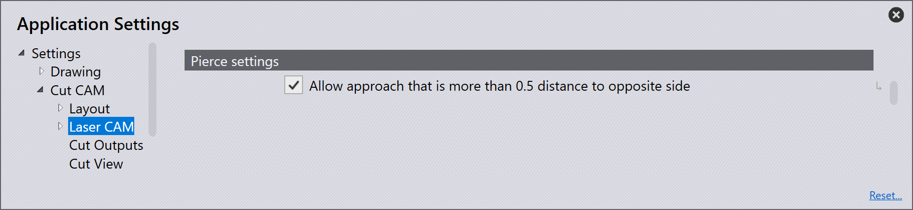
Allow approach that is more than 0.5 distance to opposite side - This option is to define whether an approach is allowed to cover more than the distance to the opposite side.
Corner processing
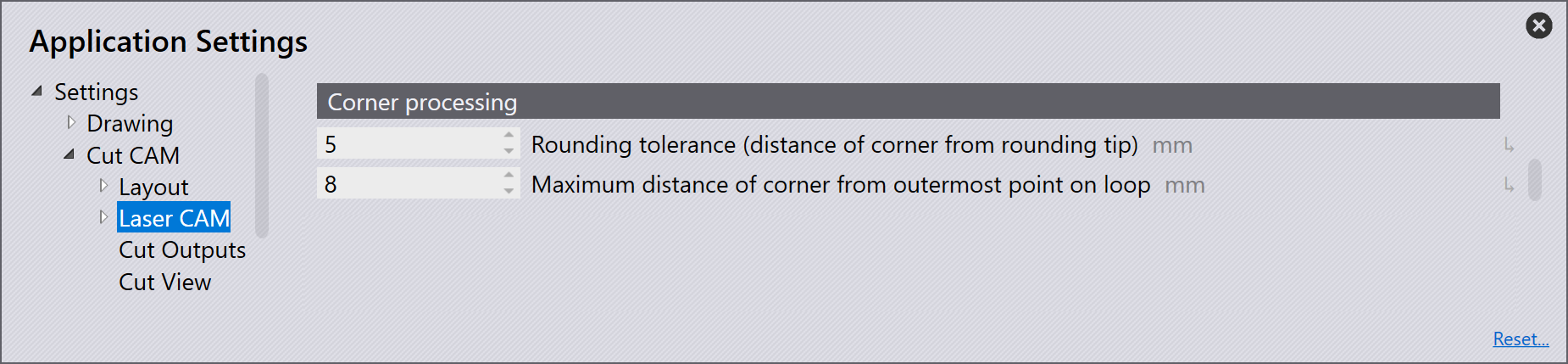
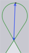
Rounding tolerance (distance of corner from rounding tip) - This option is to define the maximum distance allowed from the corner to the rounding tip as shown in the image below. The distance of the corner from the rounding tip is directly proportional to the rounding radius. Based on the value entered here, Cut will select the rounding radius in the range of min. and max. If selecting the smallest radius does not bring this distance within the tolerance value, then rounding will not be applied (looping or cooling might be applied).
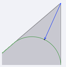
Maximum distance of corner from outermost point on loop - This option is to define the maximum extension of the loop from the corner. The loop extension is directly proportional to radius. At a sharp corner, if selecting smallest radius does not bring this distance within the value entered here, looping will not be applied (rounding or cooling might still be applied).
TwinLine
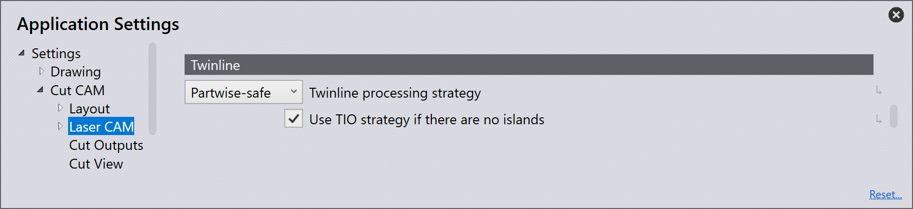
Twinline processing strategy - This drop-down is to define the twinline strategy to be used.
Partwise - The cuts are made partwise. Suitable for thick sheets where there is no rick of tipping contours.
Partwise-Safe - The cuts are made partwise, but preparatory cuts are made into adjacent parts. Suitable for thin sheets where parts could tip.
TIO (Twinline-Islands-Outer) - Twinline edges are cut first, followed by any islands created between parts and then outer contour.
Use TIO strategy of there are no islands - The software will always choose TIO (Twinline-Islands-Outer) strategy, if there are no islands created in the twinline block. This option is checked by default.
Scrap cutting
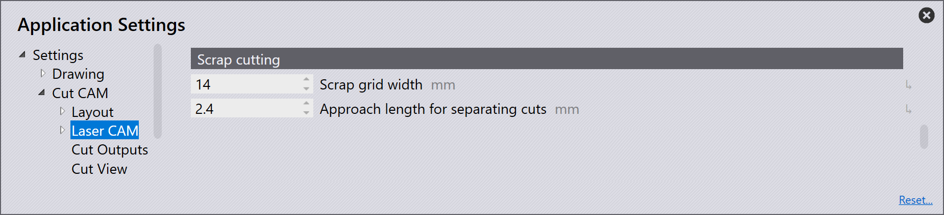
Scrap grid width - This is the width of each cell in the grid that is created by the tooling. The value entered here must be such that the resultant square is guaranteed to fall through the slats irrespective of its position.
Approach length for separating cuts - This is the length of the approached desired on scrap cuts.
Vaporization
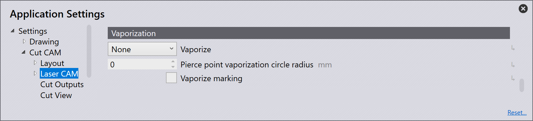
Vaporize - This setting will control if vaporization must be done or not. And, if it must be done, which portions of the laser cutting path must be vaporized.
None - No vaporization
Pierce - Only the pierce points will be vaporized
Pierce & approach - Pierce and approach portions of the laser cut path will be vaporized.
Full laser path - The entire cutting path including the pierce, approach and contour will be vaporized.
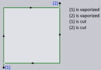
Pierce point vaporization circle radius - If a value greater than zero is entered here, the software will move the laser head in a small circle around the pierce point with the vaporizing laser on (circle vaporization). The value decides the radius of this circle. If this value is zero, vaporizing laser will be turned on exactly on top of the piercing point and then immediately turned off (point vaporization).
Vaporize marking - This option is to enable or disable vaporization. Note that laser text markings which are etched using TC_WRITE macro are never vaporized.
When these settings are modified, there will be no visible change in Cut UI except that the NC-code icon will get re-enabled if it was disabled earlier. This is because these settings have an impact on code generation. Generated vaporizing code for different cuts is described in the table below.
| Cut | Behaviour |
|---|---|
Laser Cut |
This is the usual cut item to cut a contour of the part.
If Vaporize = Pierce & approach, Only the pierce point and approach path are vaporized first and at once following that, the laser head will reposition over the pierce point and start actual cutting. For this vaporizing option and for Vaporize = Pierce, the pierce and approach are always vaporized just before executing the cut. This type of vaporization sequence is called cut-wise, as each cut piece is vaporized before it is cut. Behavior of Vaporize = Pierce, is like the above except that only the pierce points are vaporized. If Vaporize = None, there is no change in generated code. |
Scrap Cut |
If Vaporize =
Full laser path, the vaporizing and cutting sequence would be
as follows: - The entire scrap grid will be vaporized first, in the same way as it would be cut. - The contour along with its pierce and approach will be vaporized. - The scrap grid will be cut. - The contour will be cut. So, the grid and the contour, both are vaporized and then they are cut. If Vaporize = Pierce & approach or Pierce, the pierce and approach segments for scrap and contour will be vaporized just before they are cut. |
Sheet Cut |
A sheet cut will always be vaporized just before it is cut. |
FlyLine Cut |
These cuts are never vaporized, irrespective of the vaporize settings. |
Point Cut |
This will be vaporized just before it is cut. |
Laser marking
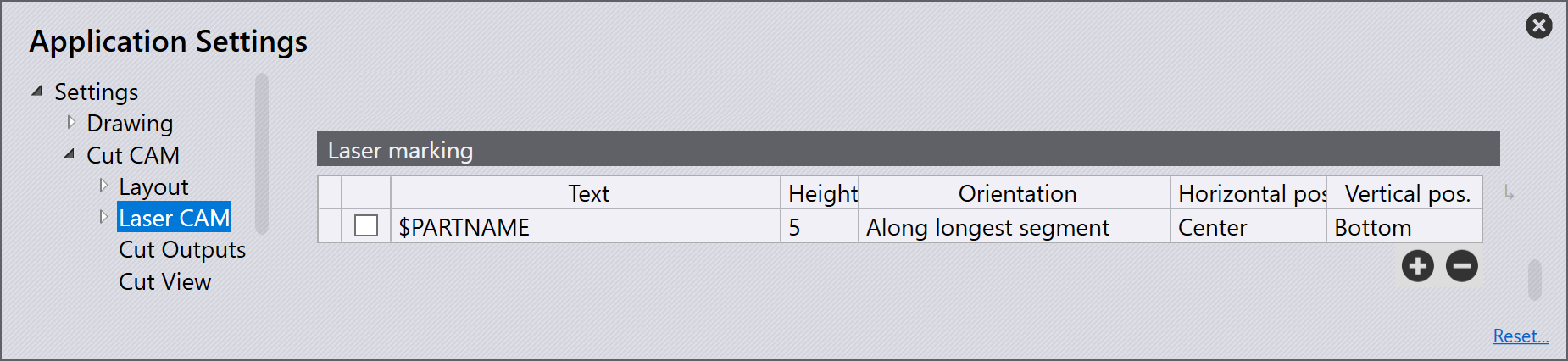
Rules for adding one or more text markings on the part can be defined in Settings → Cut CAM → Laser CAM → Laser marking. In the table shown below, user can add multiple rules, each rule leading to placement of a single line of text.

| Column | Description |
|---|---|
Checkbox |
You can enable or disable a rule using the checkbox in the first column. |
Text |
The text that must be inserted on the part. This text can contain following tokens that will be replaced with the corresponding value from Part info. These tokens are not case sensitive. $PARTNAME - Name of the part. $FILENAME - Name of the FX file. $ROOTFILE - Name of the original CAD file. $PARTID - Part identifier. $CUSTOMER - Customer. $AUTHOR - Author. $JOBNUMBER - Job number from Part→Info. These variables are indicated in a tooltip. |
Height |
This is the font height (from baseline to ascent line.) in mm or inch units. When inserting this text, it might be possible that there is not enough space to insert the text at prescribed font height. In such situations, Flux will automatically shrink the text size in steps of 10% until it is feasible to place it. This stepping down in currently allowed up-to 2 mm. Minimum has been set to 2 mm. |
Orientation |
This column determines the text orientation. Following values are possible: Horizontal - Text will be horizontal. Vertical - Text will be vertical. Along longer side: Text will be aligned with the longer side of the part. If the part is landscape, it will be horizontal and vertical if the part is portrait. Along shorter side: Text will be aligned with shorter side of the part (opposite of the above.) When adding two texts to the part, this and the previous option can be used together to minimize the risk of overlapping text. Along longest segment: Text will be aligned with the longest linear segment of the outer contour. In this case the text might not be axis aligned. Whether the text is placed horizontal, vertical or oblique, Flux will always orient the text such that the user finds the text in right direction when looking at the part from the side closest to the text. That is, horizontal text placed to bottom-center will run left-to-right and when placed to top-center will run right-to-left. |
Horizontal pos |
Horizontal alignment of text. Possible values are center, left & right. This setting is not relevant if Along longest segment is chosen as the required orientation. |
Vertical pos |
Vertical alignment of text. Possible values are center, bottom & top. This setting is not relevant if Along longest segment is chosen as the required orientation. |
When adding these marks, Flux always ensures that the added text does not collide with any part contour. For very tiny parts or parts with little open space, it will automatically scale down the font size by the required amount to fit the text inside the part and away from any holes.