
Bend navigator
When you are in the bending view, the Bend Navigator panel appears along the top edge of the Flux window. This navigator provides a quick way to navigate through various bend operations, and also a view into various status-checks for each bend. It also provides controls to view or stop the bending simulation.
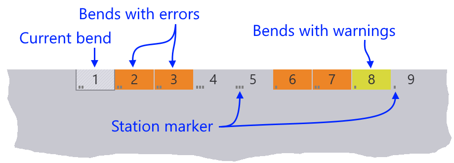
The navigator displays different colors for bends that have some warnings or errors. The current bend is displayed with an outlined box, and the small dots[1] that appear in each of the boxes indicate the tool station in which the bend is processed.
Simulation controls
When you move the mouse near the bend navigator, simulation controls appear.

-
The slider can be used to move the current bend through various phases of the bending operation (insert part, retract back-gauges, lower punch to pinch point, bend, release etc.). As the slider is moved, the tool-tip displays the current phase of bending, and various parts of the machine move in the simulation. If there are any collisions, those parts are colored red to highlight the collision.
-
The play controls near the left can be used to start the simulation, stop it, or rewind to the beginning.
-
The chevron near the middle can be used to expand the bend navigator, displaying more detailed information about the errors and warnings for various bends.
|
You can also press the Spacebar to start or stop playing the bend simulation. You can also press the Z key to expand/collapse the bend navigator display. |
Bend navigator: expanded view
When you open the bend navigator by clicking the open button, or by pressing the Z key, this is how it looks:
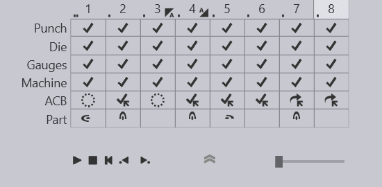
For each bend, the navigator displays several rows of status icons. Each colored icon represents an error or a warning. Moving the mouse over the colored cell displays some more information about what the error or warning is.
Clicking on a cell that displays an error poses the simulation so that the error is immediately obvious. For example, clicking on a cell that displays a punch-crash error moves the simulation to the stage of the simulation where the punch collides with the workpiece.
These are the icons that may appear adjacent to the bend numbers on the top of the navigator.
Icon |
Description |
|
Coining |
|
Double-sheet bending |
|
Hemming |
|
Pre-bend |
|
Post-bend |
|
Skipped bend |
|
Z bend |


Rows in the navigator
The navigator has multiple rows; some of these rows like Punch or Die are always displayed, while some of the others like the ACB (angle measurement) row are displayed only if the machine supports that feature.
The Punch row
The Punch row of the bend navigator displays information about the punch used for this bend, and shows if there are any punch-related warnings or errors. These are the icons that you might see in the Punch row:
Icon |
Meaning |
|
No error, valid punch used |
|
Error: Punch collides with the part during bending |
|
Error: Punch collides with the die during bending |
|
Error: Punch missing - no punch is assigned for this bend |
|
Error: Punch height is too short to complete the bend (a taller punch must be used, or an adapter added) |
|
Error: An incorrect punch process is used (for example, a non-coining punch is used for a coining operation, or a standard punch is used for a Z-bending operation) |
|
Error: Punch is overloaded beyond its rated tonnage (tooltip shows the actual load) |
|
Error: Punch span is too short (the part overhangs beyond the end of the punch) |
|
Warning: An ACB sensor is mounted at the end of the punch station |
|
Warning: ACB sensor disks are mounted too close to each other |
|
Skipped bend (no processing for this bend) |


The Die row
The Die row of the bend navigator displays information about the die used for this bend, and shows if there are any die-related warnings or errors. These are the icons you might see in the Die row:
Icon |
Meaning |
|
No error, valid die used |
|
Error: Die collides with part during bending |
|
Error: Die collides with punch during bending |
|
Error: Die missing - no die assigned for this bend |
|
Error: An incorrect die process is used (for example, a standard V die is used to process a Z-bend) |
|
Error: Die is overloaded beyond its rated tonnage (the tooltip shows the actual tonnage) |
|
Error: Die span is too short (the part overhangs beyond the end of the die) |
|
Warning: The flange might be too narrow for this die; the bending may not be accurate |
|
Skipped bend |

The Gauges row
The Gauges row of the bend navigator displays information about the back-gauges used to reference the part during bending, and also any gauge-related warnings or errors.
Icon |
Meaning |
|
No error, valid die used |
|
Error: The back-gauges collide with the part |
|
Error: The back-gauges collide with the punch or the die |
|
Error: Back-gauges not assigned for this bend |
|
Error: Back-gauge position exceeds the travel limits of the gauge |
|
Warning: Only one back-gauge used; gauging may not be stable |
|
Warning: Back-gauge position well above or below die-line; gauging may not be stable |
|
Skipped bend |


The Machine row
The Machine row of the bend navigator displays collisions or other machine related errors.
Icon |
Meaning |
|
No collisions with the machine |
|
Error: Part collides with the press beam, or with the die-bed during bending |
|
Error: Part collides with the floor during bending |
|
Error: Part collides with the bend-guard (safety system) during bending |
|
Error: Machine’s rated tonnage exceeded while processing this bend |

The ACB row
The ACB row of the bend navigator displays various ACB methods, warnings, and errors related to the angle measurement system.
Here are the icons used to display various ACB systems and modes in the bend navigator:
Icon |
Meaning |
|
Disk system, Identify method |
|
Disk system, Learn Y method |
|
Disk system, Enter SB method |
|
Laser system, Identify method |
|
Laser system, Learn Y method |
|
Laser system, Enter SB method |
|
ACB not used for this bend |


Here are the icons used to display ACB warnings and errors:
Icon |
Meaning |
|
Flange too narrow for sensor disk |
|
Sensor disk too close to edge of part |
|
Sensor disk falls into hole (risk of breakage) |
|
Invalid Reference bend (cannot learn from this bend) |
|
Laser trace length less than ideal (warning) |
|
Only one laser (front or rear) used for measurement |
|
Laser trace length too low to measure (error) |
|
Skipped bend |


The Part row
The Part row of the bend navigator displays information about part-handling. This includes information on how the part should be rotated or flipped between bends, and also warnings for situations where the part center-of-gravity falls behind the bending axis (part tip-back warning).
Icon |
Meaning |
|
No part handling issues; part does not have to be rotated or flipped. |
|
Error: An invalid bend sequence is used; the segments of this bend are not collinear and this bend cannot be processed at this position in the sequence. |
|
Warning: Part flanges collide during over-bending; angle accuracy may be compromised. |
|
Warning: Part center-of-gravity lies behind the bend line (part tipping backwards) |
|
Part has to be rotated left for the next bend |
|
Part has to be rotated right for the next bend |
|
Part has to be rotated 180°; for the next bend |
|
Part has to be flipped upside down for the next bend |
|
Skipped bend |


As you make changes to the punch, die, sequence, or gauge configurations, the bend navigator is immediately updated with the new status. This immediate feedback makes it easy to experiment with different configurations without having to issue a recompute command each time.