
Flux Reference Manual

  • Welcome to Flux
  • Introduction
    • Installing the software
    • The user interface
    • Part workflow
  • CAD
    • 2-D Import
      • 2-D Cleanup
    • 3-D Import
      • Import 3D Model
      • Import assembly
      • Form detection
      • Component detection
    • Modifying the geometry
    • Attachments
  • Laser CAM
    • Part workflow
      • Editing panels
        • Laser cut
          • Approach
          • Withdrawal
          • Microjoint
          • Advanced
        • Contour
        • Scrap cut
        • Part
        • Corner treatment
      • Quick-Nest
    • Job workflow
      • Job panel
        • Sheets tab
        • Parts tab
        • Layouts tab
        • Summary tab
      • Edit layout
        • Nesting modes
        • Placement panel
        • Sequencing
        • Slice sheet
    • Bevel cut
      • Open contours
      • Variable bevel
      • Miscellaneous
    • Advanced
      • Finishing rules
      • Edit LTT
      • FlyLine
      • TwinLine
        • Strategy
        • Microjoints
        • Further settings
      • DetectLine
  • Bend CAM
    • Create bend data
    • Bend navigator
    • Edit bend data
      • Edit a bend
      • Edit a tool mount
      • Edit a bend setup
      • Edit the back-gauges
      • Edit angle measurement
      • Bends spreadsheet
      • Changing the sequence
      • Adding setups and stations
    • Advanced
      • Angle measurement
      • Batch process
      • Recompute solution
      • Tonnage check
    • Bending Aids
  • BendMaster CAM
    • Bend navigator
    • Part pickup
      • Pickup from pallet
      • Pickup from dispenser
    • Robotic bending
      • Insertion
      • Bending
      • Extraction
    • Regripping
      • Regrip panel
      • Add regrip
      • Edit regrip
      • Regrip with jaw
      • RG-Stations panel
    • Part deposit
      • Deposit panel
      • Repeat and sequence
      • Add separator sheets
      • Lock part-rest
      • Deposit pattern types
    • Advanced
      • Waypoints
      • Cell configuration
      • Custom Cell Components
      • Gripper database
        • Create a gripper
        • Import gripper from DXF
        • Import Suction Cup
  • FlexCell CAM
    • Bend navigator
    • Part pickup
      • Pickup from pallet
      • Centering table
    • Robotic bending
      • Insertion
      • Bending
      • Extraction
      • Advanced
    • Regripping
      • Regrip panel
      • Add/Remove regrip
      • Gripper Panel
      • RG-Stations panel
    • Part deposit
      • Deposit panel
      • Deposit Tabs
    • Advanced
      • Waypoints
      • Cell configuration
      • Gripper database
        • Create a gripper
        • Import gripper from DXF
    • Troubleshooting
  • Fold CAM
    • Create fold data
    • The Fold view
    • Editing Fold data
      • Edit a bend
      • Edit a side/section
      • Change the sequence
      • Edit the blank-holders
      • Edit the gauging
      • Edit the blades
      • Edit the loading
      • Edit the unloading
    • Tool inventory
    • Advanced
      • Custom air-gap tables
      • Manual bend completion
      • Required flange length
  • Settings
    • Drawing
      • Layers
      • Dimensions
      • View
    • Bend CAM
      • Machine defaults
      • Bend outputs
      • Bend view
      • Bend cell
    • Cut CAM
      • Layout
        • Nest settings
        • Sheet
        • Sheet handling
        • Skeleton cuts
        • Work support
      • Laser CAM
        • Sequence
      • Cut outputs
      • Cut view
    • Panel bending
      • Defaults
      • ZBW carriers
      • Outputs
    • Reports
      • Item defaults
    • Import/Export
    • Environment
  • Database
    • Materials
    • Machines
    • Bend tools
    • Bend deductions
    • Bend grippers
    • Forms and Components
  • Reports
    • Report designer
    • Fields, pictures and tables
    • Bands (sub-reports)
    • Labels, bitmaps and shapes
  • Appendix
    • Supported 3D formats
    • Separator sheet DXF
    • Bend tool DXF
    • The Adapt Geometry feature
Laser CAM
/
Job workflow
/
Job panel
/
Parts tab

Parts tab

The Parts tab is used to add parts for nesting, and to set up parameters like the quantity to nest, acceptable rotation angles, etc.
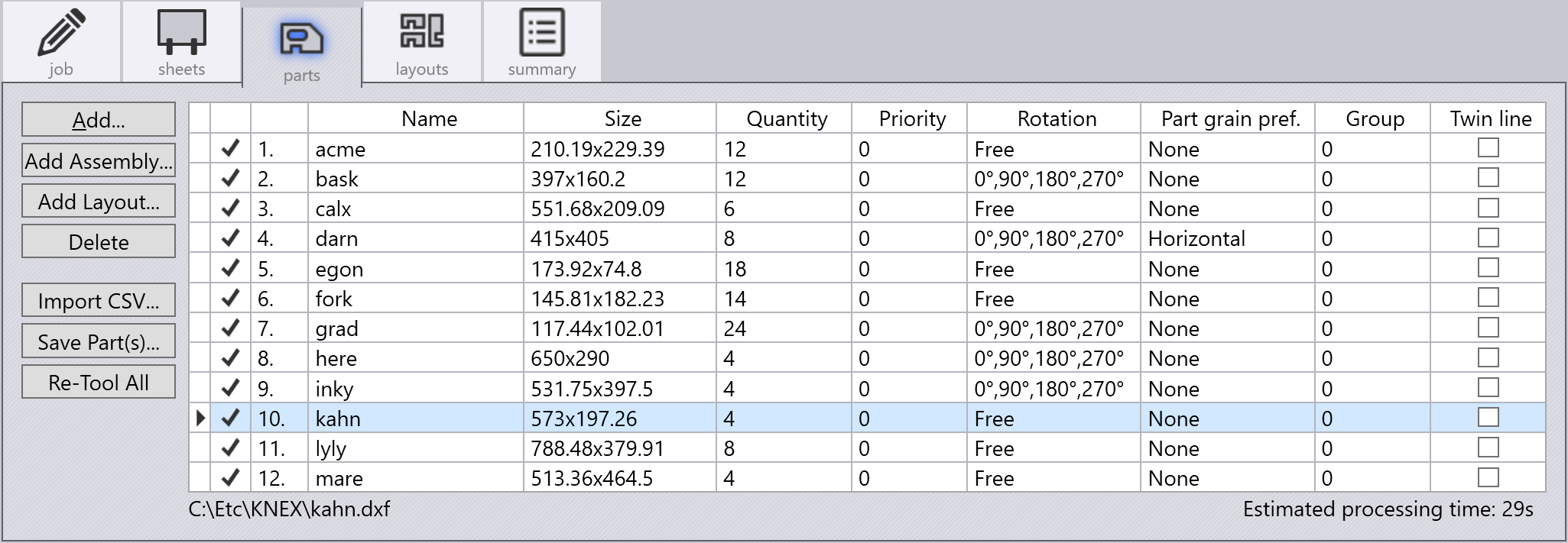
Parts Tab

Action buttons

These are the buttons along the left side of the parts panel, used to add or remove parts to the job, and to perform some operations on all the parts:

  • Use Add to add a part for nesting. This can be an already tooled up .fx file or any 2D or 3D file that Flux can import and convert to a sheet metal part.These files will then be tooled up as explained in the Part Workflow section.

  • The Add Assembly button is used to add a complete 3D assembly. Flux will select the sheet metal parts from the assembly and add them into the nesting job. The quantities for the individual components of the assembly are set to produce one quantity of the complete assembly.

  • The Add Layout button is used to import a DXF file containing a fully nested sheet, and decompose it back into a nesting job.

  • The Import CSV button is used to load a nesting job definition from a CSV (comma separated values) file. The file should have a specific format with 8 columns as explained in the tooltip below:
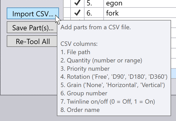
    Import CSV

  • Save Parts is used to save the selected parts as .FX files. When you start the nesting job with geometry files (like DXF, GEO, 3D data), these are tooled up automatically when added to the Parts list. This button can be used to save the tooled up versions of these parts so they can be reused in other nesting jobs.

  • The Re-Tool All is used to recompute the tooling for all the parts in the job. It is useful after you make some changes to the machine settings, or to the settings for this particular nesting job, to ensure that all the parts are using the new settings.

Parts table columns

Here are some of the columns in the part table:

  • The Quantity is the required quantity of the part. You can enter a simple number here, or a range like 20 - 30. This means that at least 20 copies of this part will be nested, but no more than 30. Flux is free to nest any quantity between these two values to maximize nesting efficiency, but will never start a new sheet just to nest parts beyond the minimum quantity.

  • Parts are nested in increasing order of Priority, if different priority values are set for different parts. However, Priority = 0 is treated as a special case - these parts have the lowest priority.

  • Part Grain Pref is used to set up the grain direction of the part if it is important. If it is set to a value other than None, that will constrain the angles at which the part can be rotated by the nesting engine. (For this to work correctly, you must also specify the grain direction of the sheets in the Sheets tab).

  • The Group value is a hint to the nesting engine - Flux will try to keep parts with the same group value together on the same sheet, where possible.

  • If the Twinline switch is turned ON for a part, the nesting engine will try to use common-line cutting for this part (the part is common-lined only with other copies of itself). Here’s an example where a nearly rectangular part uses common-line cutting in both the vertical and horizontal directions:
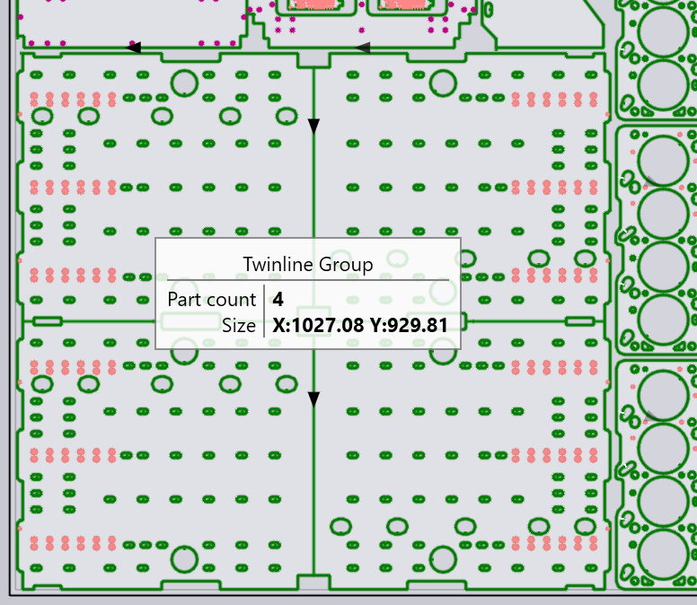
    Twin-line

Contents

  • Action buttons
  • Parts table columns
Sheets tab Layouts tab

      Copyright © 2025 TRUMPF Metamation. All rights reserved.

    Compiled by Bento