
Flux Reference Manual

  • Welcome to Flux
  • Introduction
    • Installing the software
    • The user interface
    • Part workflow
  • CAD
    • 2-D Import
      • 2-D Cleanup
    • 3-D Import
      • Import 3D Model
      • Import assembly
      • Form detection
      • Component detection
    • Modifying the geometry
    • Attachments
  • Laser CAM
    • Part workflow
      • Editing panels
        • Laser cut
          • Approach
          • Withdrawal
          • Microjoint
          • Advanced
        • Contour
        • Scrap cut
        • Part
        • Corner treatment
      • Quick-Nest
    • Job workflow
      • Job panel
        • Sheets tab
        • Parts tab
        • Layouts tab
        • Summary tab
      • Edit layout
        • Nesting modes
        • Placement panel
        • Sequencing
        • Slice sheet
    • Bevel cut
      • Open contours
      • Variable bevel
      • Miscellaneous
    • Advanced
      • Finishing rules
      • Edit LTT
      • FlyLine
      • TwinLine
        • Strategy
        • Microjoints
        • Further settings
      • DetectLine
  • Bend CAM
    • Create bend data
    • Bend navigator
    • Edit bend data
      • Edit a bend
      • Edit a tool mount
      • Edit a bend setup
      • Edit the back-gauges
      • Edit angle measurement
      • Bends spreadsheet
      • Changing the sequence
      • Adding setups and stations
    • Advanced
      • Angle measurement
      • Batch process
      • Recompute solution
      • Tonnage check
    • Bending Aids
  • BendMaster CAM
    • Bend navigator
    • Part pickup
      • Pickup from pallet
      • Pickup from dispenser
    • Robotic bending
      • Insertion
      • Bending
      • Extraction
    • Regripping
      • Regrip panel
      • Add regrip
      • Edit regrip
      • Regrip with jaw
      • RG-Stations panel
    • Part deposit
      • Deposit panel
      • Repeat and sequence
      • Add separator sheets
      • Lock part-rest
      • Deposit pattern types
    • Advanced
      • Waypoints
      • Cell configuration
      • Custom Cell Components
      • Gripper database
        • Create a gripper
        • Import gripper from DXF
        • Import Suction Cup
  • FlexCell CAM
    • Bend navigator
    • Part pickup
      • Pickup from pallet
      • Centering table
    • Robotic bending
      • Insertion
      • Bending
      • Extraction
      • Advanced
    • Regripping
      • Regrip panel
      • Add/Remove regrip
      • Gripper Panel
      • RG-Stations panel
    • Part deposit
      • Deposit panel
      • Deposit Tabs
    • Advanced
      • Waypoints
      • Cell configuration
      • Gripper database
        • Create a gripper
        • Import gripper from DXF
    • Troubleshooting
  • Fold CAM
    • Create fold data
    • The Fold view
    • Editing Fold data
      • Edit a bend
      • Edit a side/section
      • Change the sequence
      • Edit the blank-holders
      • Edit the gauging
      • Edit the blades
      • Edit the loading
      • Edit the unloading
    • Tool inventory
    • Advanced
      • Custom air-gap tables
      • Manual bend completion
      • Required flange length
  • Settings
    • Drawing
      • Layers
      • Dimensions
      • View
    • Bend CAM
      • Machine defaults
      • Bend outputs
      • Bend view
      • Bend cell
    • Cut CAM
      • Layout
        • Nest settings
        • Sheet
        • Sheet handling
        • Skeleton cuts
        • Work support
      • Laser CAM
        • Sequence
      • Cut outputs
      • Cut view
    • Panel bending
      • Defaults
      • ZBW carriers
      • Outputs
    • Reports
      • Item defaults
    • Import/Export
    • Environment
  • Database
    • Materials
    • Machines
    • Bend tools
    • Bend deductions
    • Bend grippers
    • Forms and Components
  • Reports
    • Report designer
    • Fields, pictures and tables
    • Bands (sub-reports)
    • Labels, bitmaps and shapes
  • Appendix
    • Supported 3D formats
    • Separator sheet DXF
    • Bend tool DXF
    • The Adapt Geometry feature
Reports
/
Fields, pictures and tables

Fields, pictures and tables

Clicking on the data sources opens them and display additional levels of clickable buttons. These can be used to add fields, pictures and tables to the report.

Adding a field

A field is a simple numeric or text display from the report. For example, by clicking on Part / Info / Name, you can insert a field in the report that displays the Part’s material:
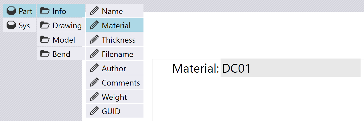
Insert Field

When you do this, Flux will actually add two items into the report - a Field displaying the value, and a Label to the left of that field. You can edit the settings for the label, or for the field, by just clicking on it.

Editing a label

When you click on the label that just got added, you will see a panel that allows you to edit various settings for that label. The label also gets highlighted and sizing handles are added around the label, allowing you to resize it by dragging any of them. You can also click right on the label and drag it around to reposition it. When you are dragging to move or resize an item, various snap indicators are automatically displayed to make it easier to align this label precisely with other items already on the report.
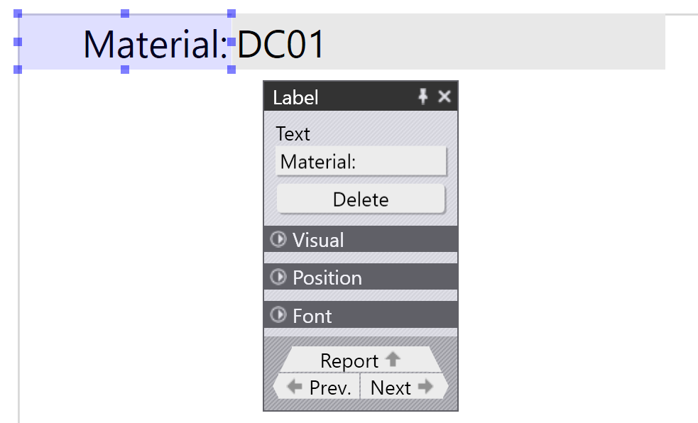
Edit Label

The editing panel for the label (and for most other report items) contains a large number of settings to tune every aspect of the visual display. You can see these by opening the various expandable groups:
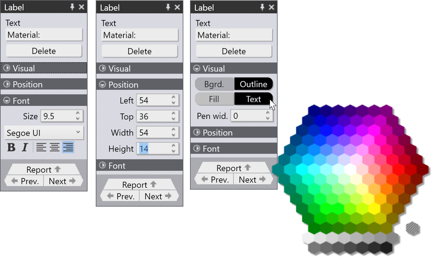
Edit Label

The image above right shows a color picker in use to set the text color for the label.

Inserting a picture

A picture in a report is indicated by a camera icon (rather than the pencil icon used for simple fields). For example, by clicking Part / Model / Picture, you can insert a picture of the 3D model of the part:
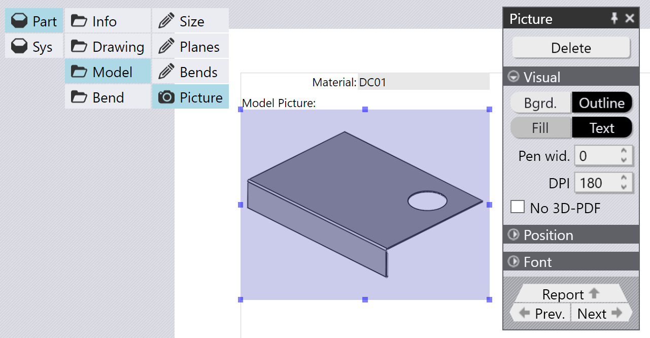
Insert Picture

The image above shows a picture inserted and then being edited by clicking on it. The panel for the picture shows some settings used to control the image. The exact settings may change, depending on the actual picture that was inserted. In this case, the DPI setting is used to control the rendering resolution of the picture (higher values will look nicer, but will cause the final report size to become larger). The No 3D PDF setting is used to disable generation of 3D PDF files[1].

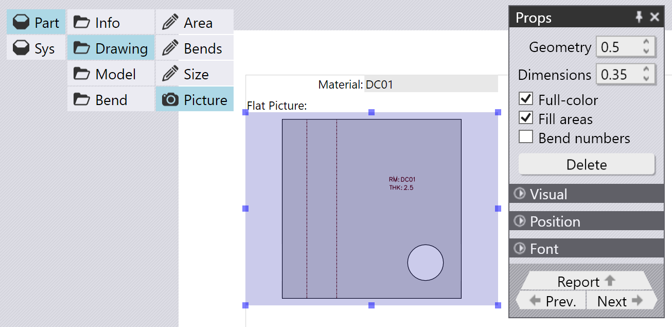
If you insert a picture of a 2D drawing (flat), the picture options are different, as seen in the image below:
Picture 2

The settings here control the line width used for outlines, and for dimensions. There are settings to display the bend sequence numbers, and to control whether the closed outline of the part is filled.

Inserting a table

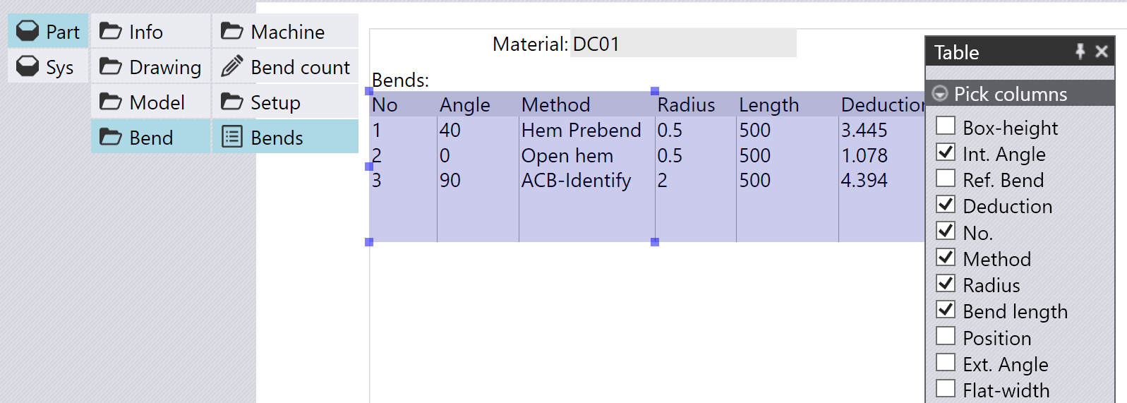
You can insert a table into a report, by choosing one of the items that displays a table icon. For example, navigate to Part / Bend / Bends / Add table to display some information about all the bend operations in a part:
Table

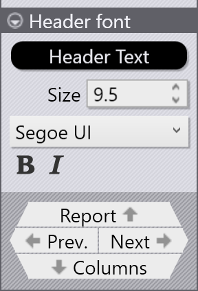
The Pick Columns section is used to select the columns that are displayed in the table (from among all the columns available for this tabular data). You can edit more attributes of each column by clicking on the Column navigation link at the bottom of the table panel:
To Columns

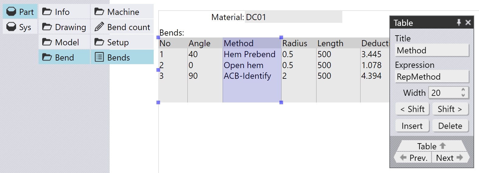
This brings up the Column editor, where the attributes of the Column can be edited, as seen below:
Columns

The Title field is used to set the displayed title for the column, while the Expression field is the internal Flux data that is displayed in this column. You can use the < Shift and Shift > buttons to shift this column left or right in the ordering, and use the Insert and Delete buttons to insert new columns, or to delete the selected column.


1. Flux can render some of its 3D images as embedded 3D PDF images; these can be zoomed, rotated or panned using some PDF viewers. However, these are not widely supported on all PDF viewers, and some of them may display these as blank boxes.

Contents

  • Adding a field
  • Editing a label
  • Inserting a picture
  • Inserting a table
Report designer Bands (sub-reports)

      Copyright © 2025 TRUMPF Metamation. All rights reserved.

    Compiled by Bento