
Flux Reference Manual

  • Welcome to Flux
  • Introduction
    • Installing the software
    • The user interface
    • Part workflow
  • CAD
    • 2-D Import
      • 2-D Cleanup
    • 3-D Import
      • Import 3D Model
      • Import assembly
      • Form detection
      • Component detection
    • Modifying the geometry
    • Attachments
  • Laser CAM
    • Part workflow
      • Editing panels
        • Laser cut
          • Approach
          • Withdrawal
          • Microjoint
          • Advanced
        • Contour
        • Scrap cut
        • Part
        • Corner treatment
      • Quick-Nest
    • Job workflow
      • Job panel
        • Sheets tab
        • Parts tab
        • Layouts tab
        • Summary tab
      • Edit layout
        • Nesting modes
        • Placement panel
        • Sequencing
        • Slice sheet
    • Bevel cut
      • Open contours
      • Variable bevel
      • Miscellaneous
    • Advanced
      • Finishing rules
      • Edit LTT
      • FlyLine
      • TwinLine
        • Strategy
        • Microjoints
        • Further settings
      • DetectLine
  • Bend CAM
    • Create bend data
    • Bend navigator
    • Edit bend data
      • Edit a bend
      • Edit a tool mount
      • Edit a bend setup
      • Edit the back-gauges
      • Edit angle measurement
      • Bends spreadsheet
      • Changing the sequence
      • Adding setups and stations
    • Advanced
      • Angle measurement
      • Batch process
      • Recompute solution
      • Tonnage check
    • Bending Aids
  • BendMaster CAM
    • Bend navigator
    • Part pickup
      • Pickup from pallet
      • Pickup from dispenser
    • Robotic bending
      • Insertion
      • Bending
      • Extraction
    • Regripping
      • Regrip panel
      • Add regrip
      • Edit regrip
      • Regrip with jaw
      • RG-Stations panel
    • Part deposit
      • Deposit panel
      • Repeat and sequence
      • Add separator sheets
      • Lock part-rest
      • Deposit pattern types
    • Advanced
      • Waypoints
      • Cell configuration
      • Custom Cell Components
      • Gripper database
        • Create a gripper
        • Import gripper from DXF
        • Import Suction Cup
  • FlexCell CAM
    • Bend navigator
    • Part pickup
      • Pickup from pallet
      • Centering table
    • Robotic bending
      • Insertion
      • Bending
      • Extraction
      • Advanced
    • Regripping
      • Regrip panel
      • Add/Remove regrip
      • Gripper Panel
      • RG-Stations panel
    • Part deposit
      • Deposit panel
      • Deposit Tabs
    • Advanced
      • Waypoints
      • Cell configuration
      • Gripper database
        • Create a gripper
        • Import gripper from DXF
    • Troubleshooting
  • Fold CAM
    • Create fold data
    • The Fold view
    • Editing Fold data
      • Edit a bend
      • Edit a side/section
      • Change the sequence
      • Edit the blank-holders
      • Edit the gauging
      • Edit the blades
      • Edit the loading
      • Edit the unloading
    • Tool inventory
    • Advanced
      • Custom air-gap tables
      • Manual bend completion
      • Required flange length
  • Settings
    • Drawing
      • Layers
      • Dimensions
      • View
    • Bend CAM
      • Machine defaults
      • Bend outputs
      • Bend view
      • Bend cell
    • Cut CAM
      • Layout
        • Nest settings
        • Sheet
        • Sheet handling
        • Skeleton cuts
        • Work support
      • Laser CAM
        • Sequence
      • Cut outputs
      • Cut view
    • Panel bending
      • Defaults
      • ZBW carriers
      • Outputs
    • Reports
      • Item defaults
    • Import/Export
    • Environment
  • Database
    • Materials
    • Machines
    • Bend tools
    • Bend deductions
    • Bend grippers
    • Forms and Components
  • Reports
    • Report designer
    • Fields, pictures and tables
    • Bands (sub-reports)
    • Labels, bitmaps and shapes
  • Appendix
    • Supported 3D formats
    • Separator sheet DXF
    • Bend tool DXF
    • The Adapt Geometry feature
Laser CAM
/
Advanced
/
DetectLine

DetectLine

The DetectLine function is useful when you are cutting prepunched sheet metal. The laser cuts must be aligned precisely with the pre-existing sheet or part edges, or with holes. When DetectLine is enabled, a camera system measures and determines the position of inserted sheets[1].

Machine configuration

To use the DetectLine function, turn on the DetectLine switch from the machine installation panel when configuring the machine.
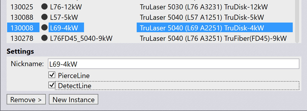
Machine Configuration

Using DetectLine

Typically, you will be using a sheet that already has some pre-punched geometry. This type of sheet will be imported from a DXF file. Let us assume we have a sheet that has two holes near the left edge. When using this sheet for a layout, you can see that Flux has already detected these pre-punched holes and has used one of the holes, and the sheet corner as measurement points.

If you bring up the Layout panel by clicking close to the boundary of the sheet, you can see the Change Measure Points button there. Pointing at the button shows some information on the currently selected measurement points, which are also indicated with red cross marks on the layout:
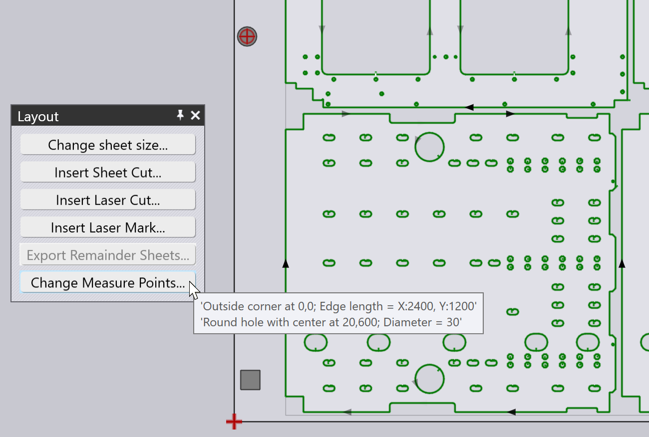
Measurement points

Clicking this button enables a mode where you can select features—such as the sheet corner, centers of pre-punched holes, or corners of pre-punched geometry—to set the measurement points. Only two measurement points can be selected at a time; if you add a third, the earliest selected point will be removed.
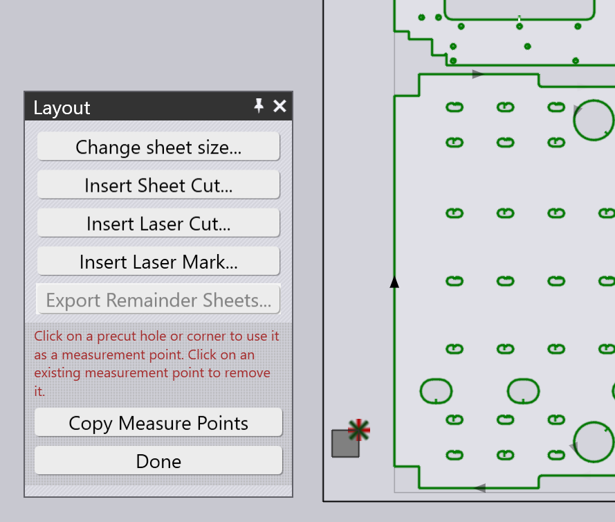
Change Measurement
  • Valid measurement points are:

    • Corners of the sheet (only one such corner point can be used).

    • Centers of pre-cut circular holes that are less than 100 mm in diameter.

    • Right angled corners of any pre-cut polygonal holes.

  • The Copy Measure Points button can be used to copy the same measurement points to all the layouts that use the same sheet.

Code generation

If this function is active, Flux adds a SHEET_MEASURE table in the code, and references it using the TC_SHEET_MEASURE command. This causes the machine to measure the holes, edges or other features used to set up this function. The laser cuts are then precisely aligned with the pre-existing geometry or edges of the sheet.


1. This function is also used to check the alignment of the laser focus position

Contents

  • Machine configuration
  • Using DetectLine
  • Code generation
Further settings Bend CAM

      Copyright © 2025 TRUMPF Metamation. All rights reserved.

    Compiled by Bento