
Flux Reference Manual

  • Welcome to Flux
  • Introduction
    • Installing the software
    • The user interface
    • Part workflow
  • CAD
    • 2-D Import
      • 2-D Cleanup
    • 3-D Import
      • Import 3D Model
      • Import assembly
      • Form detection
      • Component detection
    • Modifying the geometry
    • Attachments
  • Laser CAM
    • Part workflow
      • Editing panels
        • Laser cut
          • Approach
          • Withdrawal
          • Microjoint
          • Advanced
        • Contour
        • Scrap cut
        • Part
        • Corner treatment
      • Quick-Nest
    • Job workflow
      • Job panel
        • Sheets tab
        • Parts tab
        • Layouts tab
        • Summary tab
      • Edit layout
        • Nesting modes
        • Placement panel
        • Sequencing
        • Slice sheet
    • Bevel cut
      • Open contours
      • Variable bevel
      • Miscellaneous
    • Advanced
      • Finishing rules
      • Edit LTT
      • FlyLine
      • TwinLine
        • Strategy
        • Microjoints
        • Further settings
      • DetectLine
  • Bend CAM
    • Create bend data
    • Bend navigator
    • Edit bend data
      • Edit a bend
      • Edit a tool mount
      • Edit a bend setup
      • Edit the back-gauges
      • Edit angle measurement
      • Bends spreadsheet
      • Changing the sequence
      • Adding setups and stations
    • Advanced
      • Angle measurement
      • Batch process
      • Recompute solution
      • Tonnage check
    • Bending Aids
  • BendMaster CAM
    • Bend navigator
    • Part pickup
      • Pickup from pallet
      • Pickup from dispenser
    • Robotic bending
      • Insertion
      • Bending
      • Extraction
    • Regripping
      • Regrip panel
      • Add regrip
      • Edit regrip
      • Regrip with jaw
      • RG-Stations panel
    • Part deposit
      • Deposit panel
      • Repeat and sequence
      • Add separator sheets
      • Lock part-rest
      • Deposit pattern types
    • Advanced
      • Waypoints
      • Cell configuration
      • Custom Cell Components
      • Gripper database
        • Create a gripper
        • Import gripper from DXF
        • Import Suction Cup
  • FlexCell CAM
    • Bend navigator
    • Part pickup
      • Pickup from pallet
      • Centering table
    • Robotic bending
      • Insertion
      • Bending
      • Extraction
      • Advanced
    • Regripping
      • Regrip panel
      • Add/Remove regrip
      • Gripper Panel
      • RG-Stations panel
    • Part deposit
      • Deposit panel
      • Deposit Tabs
    • Advanced
      • Waypoints
      • Cell configuration
      • Gripper database
        • Create a gripper
        • Import gripper from DXF
    • Troubleshooting
  • Fold CAM
    • Create fold data
    • The Fold view
    • Editing Fold data
      • Edit a bend
      • Edit a side/section
      • Change the sequence
      • Edit the blank-holders
      • Edit the gauging
      • Edit the blades
      • Edit the loading
      • Edit the unloading
    • Tool inventory
    • Advanced
      • Custom air-gap tables
      • Manual bend completion
      • Required flange length
  • Settings
    • Drawing
      • Layers
      • Dimensions
      • View
    • Bend CAM
      • Machine defaults
      • Bend outputs
      • Bend view
      • Bend cell
    • Cut CAM
      • Layout
        • Nest settings
        • Sheet
        • Sheet handling
        • Skeleton cuts
        • Work support
      • Laser CAM
        • Sequence
      • Cut outputs
      • Cut view
    • Panel bending
      • Defaults
      • ZBW carriers
      • Outputs
    • Reports
      • Item defaults
    • Import/Export
    • Environment
  • Database
    • Materials
    • Machines
    • Bend tools
    • Bend deductions
    • Bend grippers
    • Forms and Components
  • Reports
    • Report designer
    • Fields, pictures and tables
    • Bands (sub-reports)
    • Labels, bitmaps and shapes
  • Appendix
    • Supported 3D formats
    • Separator sheet DXF
    • Bend tool DXF
    • The Adapt Geometry feature
Appendix
/
The Adapt Geometry feature

The Adapt Geometry feature

This document explains the three different process options available with the Adapt Geometry feature:
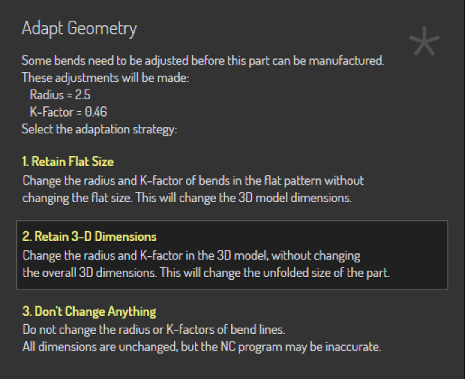
Adapt Geometry Dialog

The Adapt Geometry function is called upon when the input part does not match the actual process conditions. One or both of these problems may exist with the part:

  • The inner radius of the bends may be too small. Each process (like panel-bending, or press-brake air-bending) will have minimum inner radius that is possible with that process. If the design radius of the part is smaller than this, the part cannot be manufactured as designed; the radius will need to be changed.

  • The K-factor of the bend line may be incorrect. The process machine (panel-bender vs press-brake) and the process tools or conditions (punch/die/folding blade/air-gap) all combine to dictate what the actual K-factor of the bend will be. The bend may be designed with a different K factor.[1]

Let us take a simple 2-D part that has both an incorrect radius and an incorrect K-factor, and see how the Adapt Geometry function modifies this part.
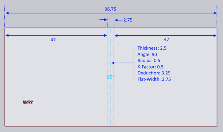
2D Part
Figure 1. 2D Part

The input 2D part is shown above - it is a simple rectangle with one bend-line exactly down the middle. The part width is 96.75 mm. Material thickness is 2.5mm

The bend line has been designed with an inner radius of 0.5, and a K-factor of 0.5. The flat-width (length of the neutral line) is therefore:

angle * (innerRadius + kFactor * thickness) = PI/2 * (0.5 + 0.5 * 2.5) = 2.75 mm

Since this is a 90 degree bend, the bend deduction is simply:

2 * thickness - flatWidth = 2 * 3 - 2.75 = 3.25 mm

Don’t Change Anything

When folded up without any Adapt Geometry processing, this therefore creates a part with these dimensions:
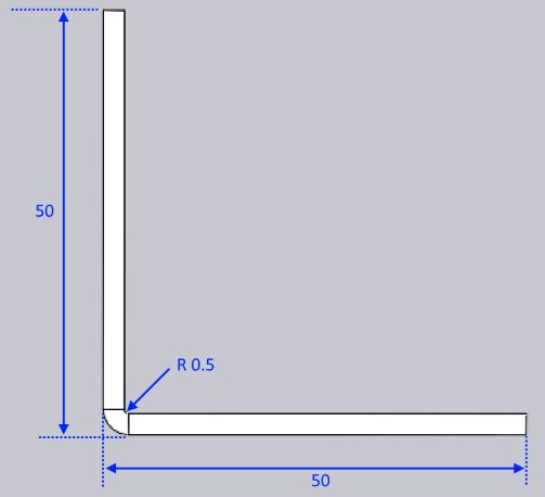
Dont Change Anything
Figure 2. Don’t Change Anything

This is also exactly the result we get with the option Don’t Change Anything. Neither the K-factor nor the radius were changed, resulting in a 3D part that matches exactly the design intent of the 2D drawing. If this is set for manufacturing, the resulting manufactured part will not actually match these dimensions, mainly because the bend produced on the machine will vary both in radius and effective K-factor than the bend that was designed. In this case, you will end up with a part that is a bit smaller than 50x50 after manufacturing.

Retain Flat Size

If this option is chosen, Flux will keep the flat’s size unchanged, but will annotate the bend lines with the correct bend radius and K-factor. Let us assume that the correct bend radius is 2.5mm and the K-Factor is 0.46 mm. The part would now first be changed internally to this:
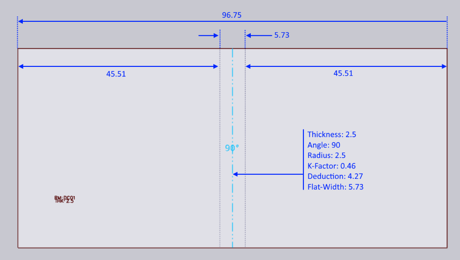
Retain Flat Size
Figure 3. Retain Flat Size

Note how the overall part size is unchanged (still 96.75 mm), and the position of the bend line is unchanged. However, the bend is now of radius 2.5, and K-factor 0.46, which means the bend’s flat width has increased to 5.73. This is now folded up to result in the following:
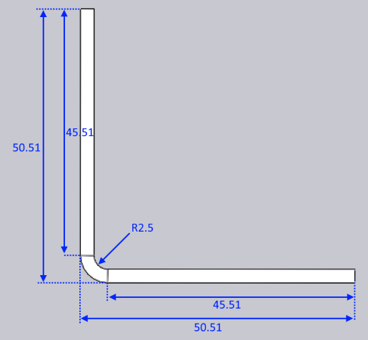
Retain Flat Size2
Figure 4. Retain Flat Size2

As you can see, the 2D dimension of the part is unchanged, but the 3-D dimension has changed to 50.51 x 50.51 (from the initial design dimension of 50 x 50).

Retain 3-D Dimension

If this option is chosen, the part’s 3D dimension is unchanged, but since the bend radii and K-factors are changed, the unfolded part will change. When starting with a 2-D flat (as in this example), Flux follows the following steps.

  • Fold the model to 3D, using the initial design intent of radius and K-Factor. This will result in a 3D model that looks identical to the one in Figure 2.

  • Now, change the radius to the target radius of 2.5mm and the K-factor to the target of 0.46. This will result in a 3D model like the one below:
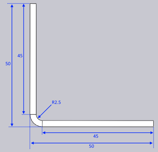
Retain 3D
Figure 5. Retain 3D
  • This model is then unfolded (using a K-factor of 0.46 for the bend) to result in the following flat:
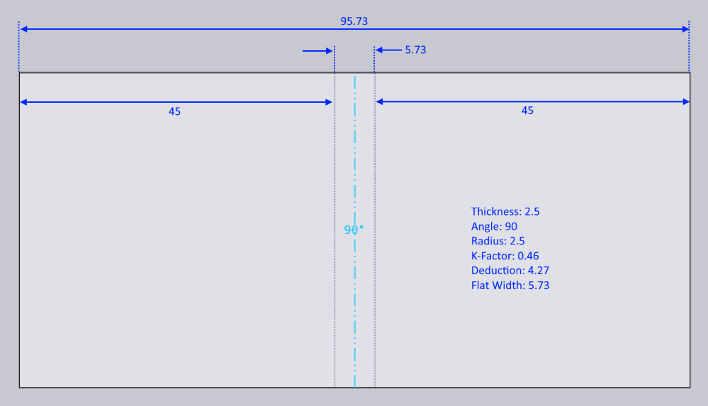
Retain 3D2
Figure 6. Retain 3D2

With this option, the 3D dimension is retained at the design dimension of 50x50. The unfolded part width has changed from 96.75 to 95.73 mm.

Summary

  • If the flat has not yet been produced, the best option is typically Retain 3-D Dimension

  • If the flat has been produced and cannot be modified, the best option is Retain Flat Size

Both these options will result in parts where the final manufactured result should match the 3D data as seen in the Flux window. In contrast, the Don’t Change Anything option will result in a final manufactured part that will not match the 3D data seen in Flux, since the actual bend radii and K-factors are not modeled correctly in the design.


1. Note that this is typically an issue only with 2-D parts. 3-D parts have a bend-radius associated with each bend, but do not define a K-factor yet. It is only during the process of unfolding that a K-factor needs to be set, thus dictating the 'bending allowance' of each bend as it is unfolded to the flat.

Contents

  • Don’t Change Anything
  • Retain Flat Size
  • Retain 3-D Dimension
  • Summary
Bend tool DXF

      Copyright © 2025 TRUMPF Metamation. All rights reserved.

    Compiled by Bento