
Bend tool DXF
Flux ships with a wide variety of bend tool catalogs (like Trumpf, Wila, Wilson, Rolleri, Amada etc). If you are using tools from any of the approximately 40 different tool catalogs that Flux provides, you can simply install the catalog and start using the tools. Occasionally, it is necessary to model a custom tool, or a tool that is from a catalog not represented in Flux.
The Bend-Tool DXF Format is the standard mechanism by which this is done. Flux can now export bend tools to DXF format, and can also import bend tools from a DXF format. The DXF files used to represent bend tools must follow certain rules so Flux can gather all the information it needs. Very often, a quick way of creating a bend tool is to use the Export to DXF function to create a DXF file from an existing tool. Then, the DXF can be edited (either in Flux, or in any other 2D CAD system). Finally, the modified DXF can be fed back into Flux using the Import from DXF function.
Example DXF
Here is an example of a bend tool DXF that was created using the Export to DXF command:
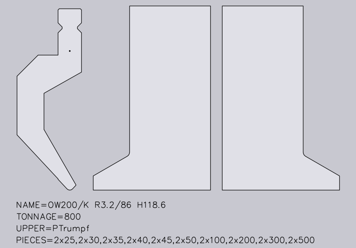
The tool DXF must contain:
-
One closed shape (made of lines, arcs, polylines) that defines the side-profile of the tool. This profile pline must be the left-most closed POLYLINE in the drawing (see figure above).
-
A POINT entity marking the reference point of the tool. This point entity must lie somewhere within the closed profile polyline, and indicates the point from which the height of the tool is measured (see image above).
-
For each tool piece that is not a simple rectangle in the front view, a front-view drawing is required. These are typically left or right-ear pieces, but could also be custom pieces, including window pieces.
-
Each front view drawing must appear to the right of the profile drawing and must be horizontally aligned with it. Each front view must have exactly the same height as the side-profile drawing; else it will not be considered. The image above shows a typical example with a left-ear and a right-ear piece.
-
Other information about the tool is indicated using text strings (see the notes below).
Metadata in text entities
Any text strings that are in the format KEY=value are read by the tool-exporter and parsed to obtain additional information about the tool. These are the keys that are supported now:
NAME=OW200/K R3.2/86 CUSTOM-A
Specifies the name of the tool. This is mandatory.
TONNAGE=800
Specifies the maximum loading of the tool, in kN/m. This is mandatory, if you want to
avoid spurious tool-overload errors from being displayed.
UPPER=PTrumpf
This is necessary for punches, and specifies the connector type (the mounting type of this
tool on the press beam). The connection types supported are listed below:
| Name | Meaning |
|---|---|
PTrumpf |
Trumpf punch (Modufix connector) |
PAmada |
Amada punch |
PWila |
Wila classic punch |
PWilaNS |
Wila New-Standard punch |
PAmerican |
American (US type) punch |
PEHT |
EHT punch |
PLVDA |
LVD size A punch |
PLVDB |
LVD size B punch |
PLVDC |
LVD size C punch |
PLVDD |
LVD size D punch |
PGasparini |
Gasparini punch |
PBayelerR |
Bayeler R-type punch |
PBayelerS |
Bayeler S-type punch |
PUrsviken |
Ursviken OEM punch |
PBayelerEuro |
Bayeler Euro punch |
PColgar |
Colgar punch |
PKomatsu |
Komatsu punch |
LOWER=DTrumpf
This is necessary for dies, and specifies the connector type (the mounting
type of this tool on the die bed). The connection types supported are listed below:
| Name | Meaning |
|---|---|
DTrumpf |
Trumpf Die |
DAmada30 |
Amada die, 30 mm wide |
DAmada60 |
Amada die, 60 mm wide |
DAmadaF |
Amada die, flat |
DAmada2V |
Amada 2-V die |
DAmadaQuick |
Amada quick-change die |
DAmada90 |
Amada die, 90 mm wide |
DEHT |
EHT die |
DAmada120 |
Amada die, 120 mm wide |
DWeinbrenner |
Weinbrenner die |
DWila |
Wila die |
DKomatsu |
Komatsu die |
DBeyeler110 |
Beyeler 110 mm die |
DLVD |
LVD die |
PIECES=2x25,30,45,50,2x100,200,4x500
This specifies the standard pieces for this tool (the left-ear and right-ear
pieces are already specified by drawing their profiles). The list is a set of
comma separated piece-lengths, and optionally each length may have a quantity
multiplier in front of it. So, the list above defines that there are 2 pieces
of 25 mm, 1 piece of 30 mm, 4 pieces of 500 mm etc.
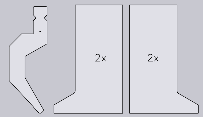
| If you want a quantity multiplier for the special shaped pieces (like the ear pieces), just add a text entity of the form 2x inside that piece’s outline: |
VWIDTHTYPE=Sharp
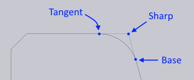
This is necessary for dies whose V-width definition does not match with Trumpf (see the
image below):
| Name | Meaning |
|---|---|
Sharp |
Theoretical-sharp of the die |
Tangent |
Top-tangent point |
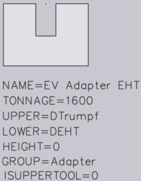
ISUPPERTOOL=0
Specifies if the tool is an upper or lower tool. For upper tool the value should be 1
and for lower tool it should be zero. This is necessary for tools that have to be
imported with zero height (see the image below):
Shape recognition
In the bend tool DXF format, note that it is not necessary to specify some critical parameters of the punch/die such as the height, radius, angle or V-width. Flux analyzes the tool drawing and extracts these parameters automatically. For a punch, Flux expects to find a curved segment at the bottom (bc) flanked by straight lines (ab and cd).
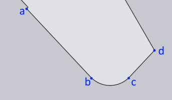
From these three segments, the angle and radius of the punch are automatically recognized. For a die, Flux examines the left shoulder to extract the parameters. It expects to find a curved shoulder segment (bc) flanked by a horizontal top (ab) and the inclined angle segment (cd).
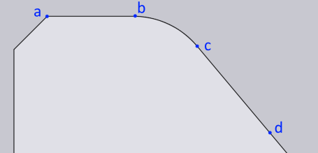
If the punch or die do not meet these shape-recognition requirements, Flux will not be able to recognize the shape as a punch or a die.
Additional information:
-
The tool profile may appear anywhere in the drawing - the precise location is not important since the point marker entity is used to provide the reference point of the tool.
-
In addition to the entities mentioned above, there should not be any other entities in the drawing. In particular, there should not be a title block, or any closed polylines in the drawing.
-
The drawing should always be in metric units (regardless of the current operating unit of Flux).
-
While the command says Import from DXF, Flux will also accept a GEO file instead, provided it follows the same conventions listed above.
Special tools
The tool importer can recognize certain types of special tools. These need to be identified using a text in the form of FLAVOR=XYX in the DXF file.
Hem punches
For a hem punch, the following additional entries are required:
-
The text FLAVOR=HemPunch marks this as a hemming tool.
-
The text PARAMS=-1,12.15,70 provides some metrics that are required for correct simulation.
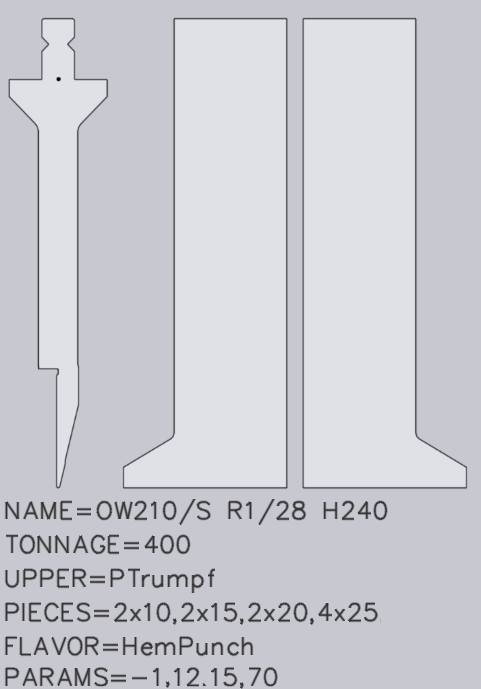
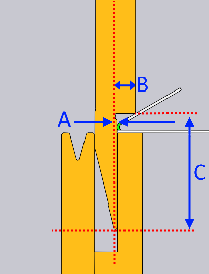
There are three parameters required to define the hemming process. These can be seen as the A, B and C values in the image above. The first (-1 mm in this example) defines how far behind the bending line the flat vertical-face of the punch is. In this case, since the flat vertical face is ahead of the bending line, the value is -1. The second parameter (12.15 mm here) defines how far ahead of the bending line the hemming tip is. The final parameter (70 mm here) is the vertical distance from the punch tip to the hemming tip point.
Hem block dies
A hemming block is an attachment that is mounted in front of a die, or behind a die for hemming. This provides a flat surface against which a hemming may engage, in order to do a clean hem.
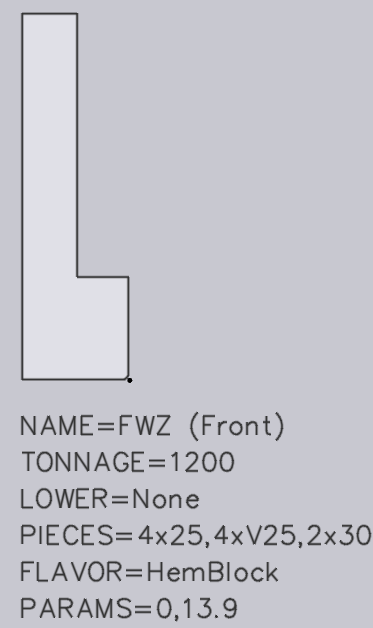
For a hem block, the following additional entries are required:
-
The text FLAVOR=HemBlock marks this as a hem block.
-
The text PARAMS=0,13.9 provides some metrics that are required for correct simulation.
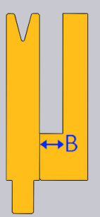
Two parameters are required to define the hemming block. The first parameter defines the hemming position whether this block should be used in front of the die or behind the die. 0 = front and 1 = back. The above example shows that the block can be used in front of the die. The other parameter is the hemming displacement which is the I axis movement. This is shown as B in the image above.
Z-Bend dies
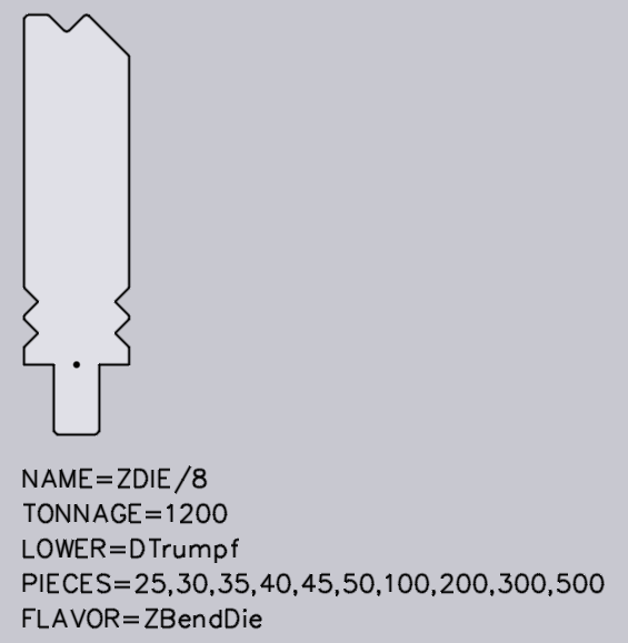
For a Z-Bend die, the following additional entries are required in DXF file:
-
The text FLAVOR=ZBendDie marks this as a Z-Bend die.
-
The text PARAMS=5.66,2.83,90,90,45 provides some metrics that are required for correct simulation.
The 5 parameters defined in PARAMS are as per the image below:
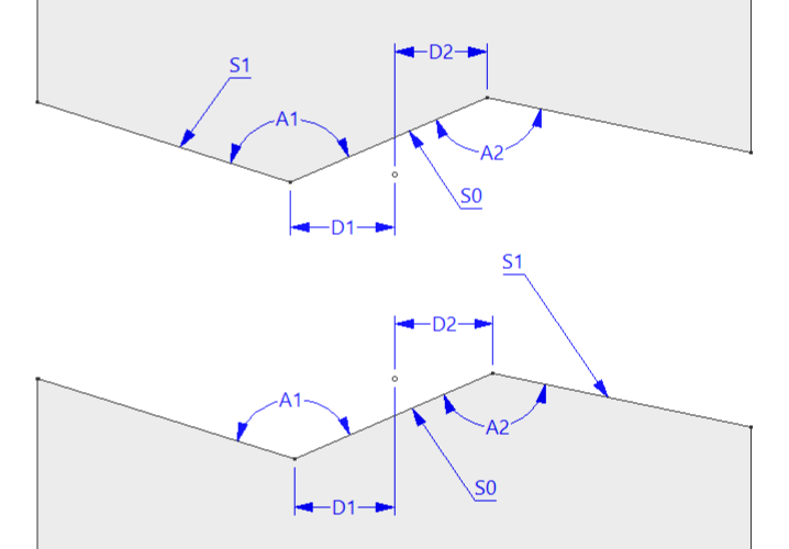
1 = Total distance (D1+D2)
2 = Right distance (D2)
3 = Angle above (A1)
4 = Angle below (A2, A1==A2 for a symmetrical Z bend tool)
5 = Slope at center (S0)
In addition, the tool should be drawn so that the central flat span goes from bottom-left to top-right. In other words, the orientation should be as shown in the image below, and not the flipped orientation of this:
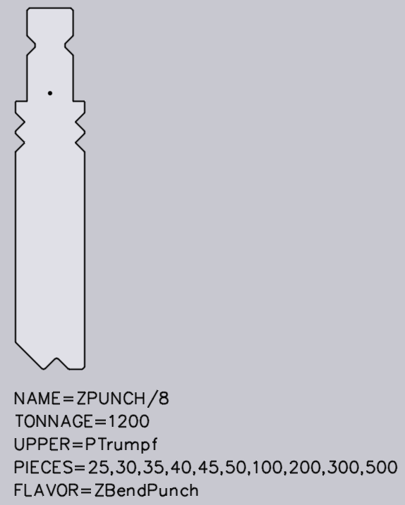
Z-Bend punches
For a Z-Bend punch, the following additional entries are required in DXF file:
-
The text FLAVOR=ZBendPunch marks this as a Z-Bend punch.
-
The text PARAMS=5.66,2.83,90,90,45 provides some metrics that are required for correct simulation. This is same as the PARAMS defined for Z-Bend die.
In addition, the tool should be drawn so that the central flat span goes from bottom-left to top-right. In other words, the orientation should be as shown in the image below, and not the flipped orientation of this:
Radius punches
This is a radius shaft that needs a radius holder.
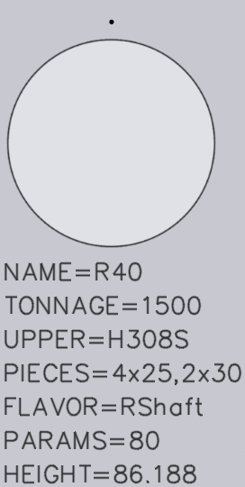
For such punches, the following additional entries are required:
-
The text FLAVOR=RShaft marks this as a radius-shaft.
-
The text PARAMS=80 is the height of the tool to be output in the NC program.
| The POINT entity is the reference point of the tool. The tool should be drawn so that the reference point is where the tip of inverted V of the holder is. |
-
Draw the radius insert with the relevant holder as it is mounted in the machine as shown below:
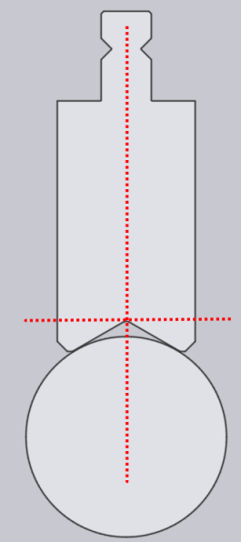
-
Remove the holder pline and save the radius insert dxf. Only the POINT entity at the tip of inverted V of the holder and the insert pline, little down from the POINT will be the profile dxf for this insert.
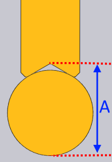
-
Height of this tool is measured from the POINT entity. This is shown as A in the image below.
EV-F hem dies
These are EV-F tools which are used to do hemming without displacement. Such a die is called an I0HemDie.
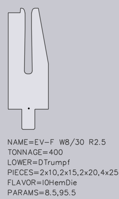
For such dies, the following additional entries are required:
-
The text FLAVOR=I0HemDie marks this as I0HemDie.
-
The text PARAMS=8.5,95.5 provides some metrics that are required for correct simulation.
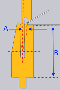
There are two parameters defining this hemming die. These can be seen as the A and B values in the image above. The first parameter (8.5 mm in this example) defines how far the part is during hemming from center line. The second parameter (95.5 mm here) defines the vertical distance from where the part lies during hemming to the bottom of the die.
EV-F hem punches
These are EV-F punches which are used to do hemming without displacement. Such a punch is called I0HemPunch.
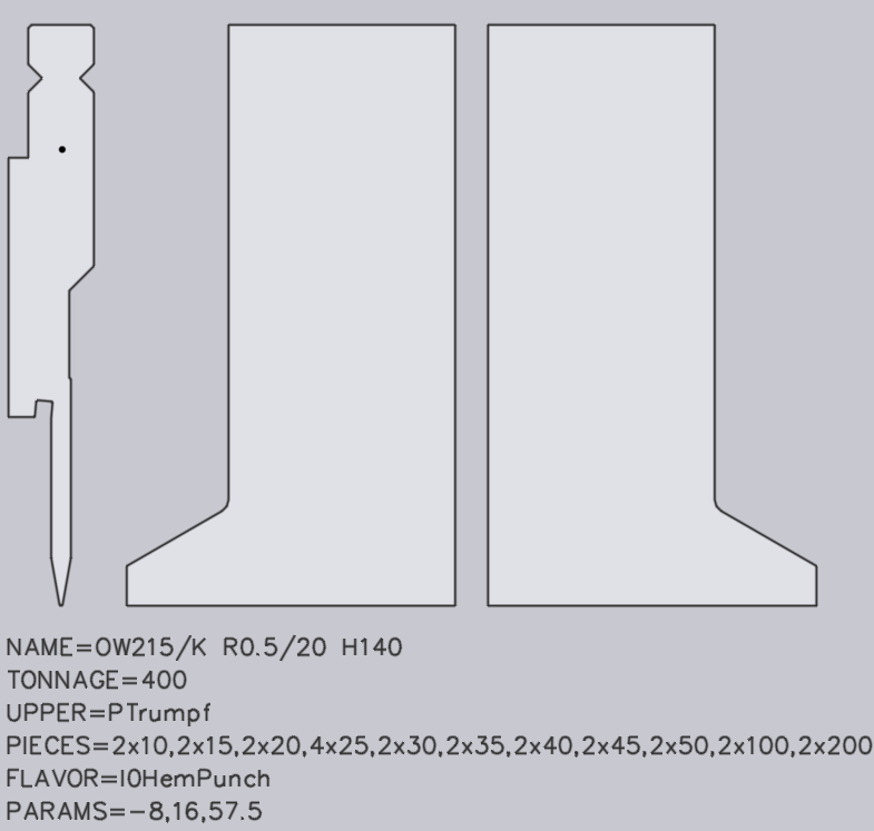
For such punches, the following additional entries are required:
-
The text FLAVOR=I0HemPunch which marks this as a I0HemPunch.
-
The text PARAMS=-8,16,57.5 provides some metrics that are required for correct simulation.
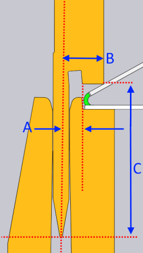
There are three parameters required to define the hemming process. These can be seen as the A, B and C values in the image above. These parameters are same as that defined in HemPunch.
Roll-Bend dies
Roll-bend die is called as wing die.
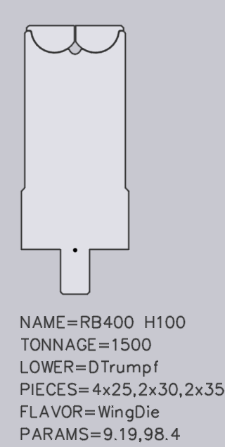
This tool requires the following additional entries:
-
The text FLAVOR=WingDie which marks this as a wing tool.
-
The text PARAMS=10.49,100 provides some metrics that are required for correct simulation of the wings.
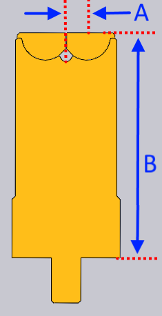
There are two parameters defining the movement of the wing-bend pieces. The first parameter is the horizontal distance from the center-line of the die to the center-point of rotation of one of the wings. This is shown as A in the picture above. The second parameter is the vertical distance from the bottom of the die to the center-point of rotation of the wings. This is shown as B in the picture above. Normally, B and Height will be the same.
Self hem dies
These are V-dies that also have a separate hemming table like the image below. For this die, there should be a text entry like this in the DXF file: FLAVOR=SelfHemDie
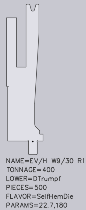
In addition, the PARAMS entry is required which has two values. These two parameters are same as that of I0HemDie.
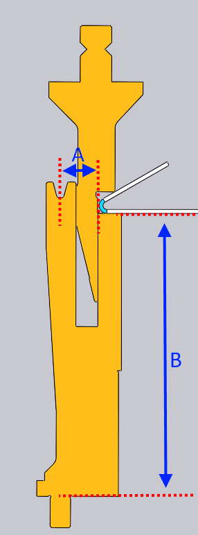
These can be seen as the A and B values in the image above. The first parameter defines how far the part is during hemming from center line. The second parameter defines the vertical distance from where the part lies during hemming to the bottom of the die.
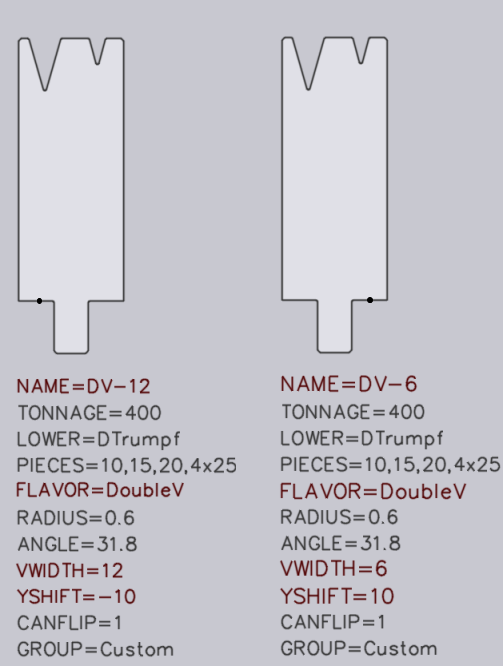
Double V dies
Dies that have multiple V widths which need IAxis to use the other V are referred as double V dies. There are few rules to follow:
-
Create dxfs for dies with the FLAVOR=DoubleV setting one for each V-width
-
Set the same ORDERNO for both the dies (this can be any non-empty string)
-
Set the YSHIFT value to the correct IAxis value to use
-
Draw a point marker at the bottom of the die, centered under the V to indicate where the forming geometry is
For example, a die with V-widths 12 and 6, has to be created as two DXFs as shown in the image below:
Spring-loaded hemming dies (feather-hemming-dies)
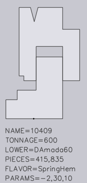
For a spring-loaded hemming die, there should be a text entry like this in the DXF file: FLAVOR=SpringHem
In addition, the following additional entry is required:
-
The text PARAMS=-2,30,10 provides some metrics that are required for correct simulation.
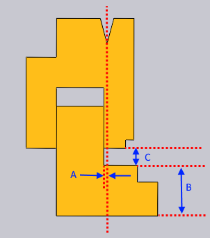
This die is a two-piece die which has a top part that moves downwards to flatten the hem. There are three parameters that define the flattening notch. The first parameter is the distance from the center-line of the die for the part during hemming. A +ve value means that it is to the front of the center-line and -ve value means that it is to the back of the center-line. This is shown as A in the picture above. The second parameter is the location of the flattening notch from the base of the die for the part during hemming. This is shown as B in the picture above. The third parameter is the spring gap which is the height of the notch. This is shown as C in the picture above.
Flat dies
Flat dies along with flat punches have a flat surface against which a hemming
may engage, in order to do a clean hem.
Helper / auxiliary bend can also be flattened by these tools.
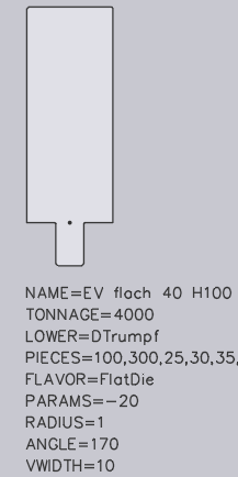
For a flat die, the following additional entries are required:
-
The text FLAVOR=FlatDie marks this as a flat die.
-
The text PARAMS=-20 provides some metrics that are required for correct simulation.
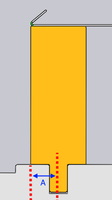
This parameter defines how far the part is during hemming from center line. This is shown as A in the image above.
Flat punches
For a flat punch, there should be a text entry like this in the DXF file: FLAVOR=FlatPunch
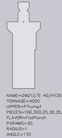
In addition, the following entry is required:
-
The text PARAMS=20 provides some metrics that are required for correct simulation. This parameter defines how far the part is during hemming from center line similar to the flat die.
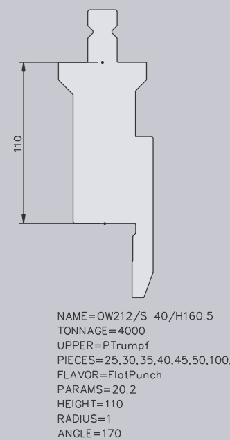
For some flat punches the height might not be the total profile length. Hence for these punches, height has to be mentioned specifically as shown in the image below:
Flat inserts
Flat inserts (dies / punches) which need IAxis to do a clean hem can also be imported into Flux.
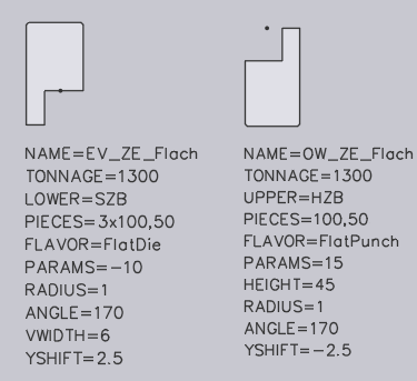
In addition to the FLAVOR and PARAMS entries for flat die / flat punch, YSHIFT value should be set, so that correct IAxis value can be used. Refer the image below:
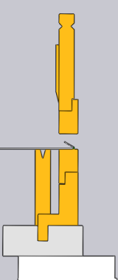
Punch Adapters
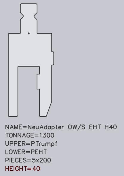
The tool importer can import punch adapters. For Flux to recognize correctly that the drawing is a punch adapter, there should be the following text entities in the file:
-
A text like UPPER=PTrumpf marking the upper mounting type (typically, this is PTrumpf if the adapter is to be mounted on a Trumpf machine).
-
A text like LOWER=PEHT marking the lower mounting type (this is the type of punch that can be mounted on the adapter).
-
A text like HEIGHT=64 that maps the effective working height of the adapter. This is necessary, since Flux cannot infer the height of adapter automatically.
Here is an image of a punch adapter that can be imported from DXF:
Blade Holders
The tool importer can import blade holders. Some blade holders (for example, the ones similar to OW209/S) are also hemming punches used to flatten a hem. For such blade holders, some additional data is required
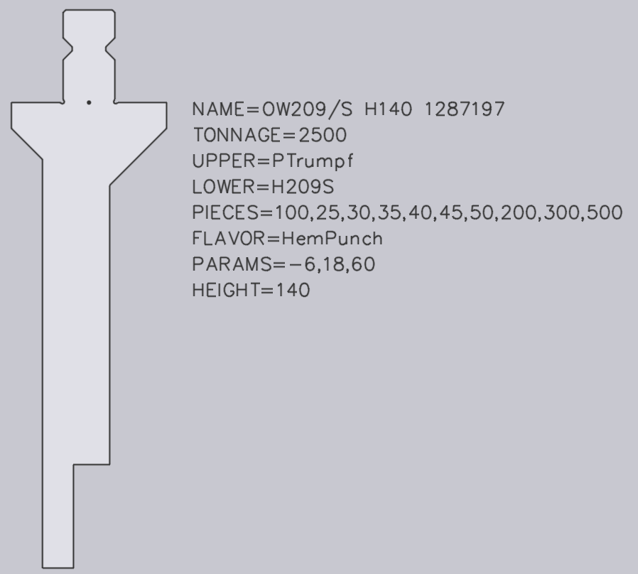
The mandatory parameters UPPER, LOWER, HEIGHT are explained in the section above on Punch Adapters, and they have the same meaning. In addition, to help Flux to use the holder as a hemming tool, the following additional entries are required:
-
The text SPLFLAVOR=HemPunch marks the adapter as a hemming tool.
-
The text PARAMS=-6,18,60 provides some metrics that are required for correct simulation of the hemming process.
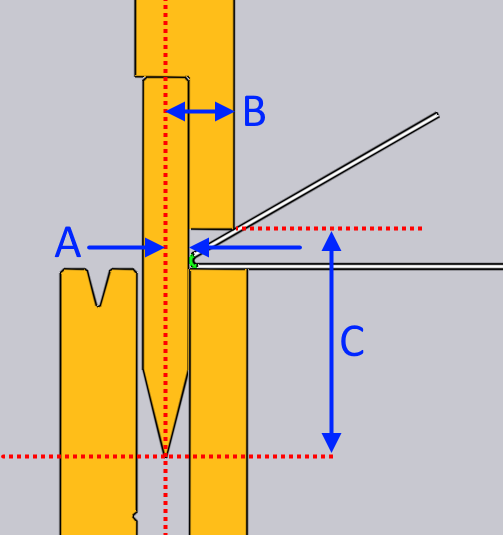
There are three parameters required to define the hemming process. These can be seen as the A, B and C values in the image above. The first (-6 mm in this example) defines how far behind the bending line the flat vertical-face of the punch is. In this case, since the flat vertical face is ahead of the bending line, the value is -6. The second parameter (18 mm here) defines how far ahead of the bending line the hemming tip is. The final parameter (60 mm here) is the vertical distance from the punch tip to the hemming tip point.
Radius holders
This is the holder for radius-shaft tools.
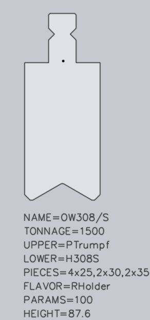
The following additional entries are required:
-
The text FLAVOR=RHolder marks the adapter as a radius-shaft holder.
-
The text PARAMS=100 is the height of the tool to be output in the NC program.
-
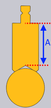
Height of this tool is measured from the origin to the inverted V of the holder. This is shown as A in the image below.
Double V holders
These are die holders that can hold 2 dies.
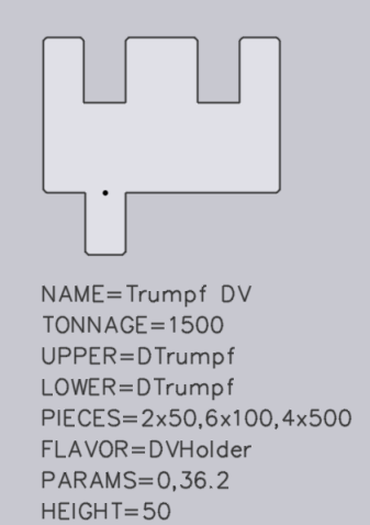
The following additional entries are required:
-
The text FLAVOR=DVHolder marks the adapter as a DVHolder.
-
The text PARAMS=0,36.2 provides metrics to shift die to the other slot in the holder.
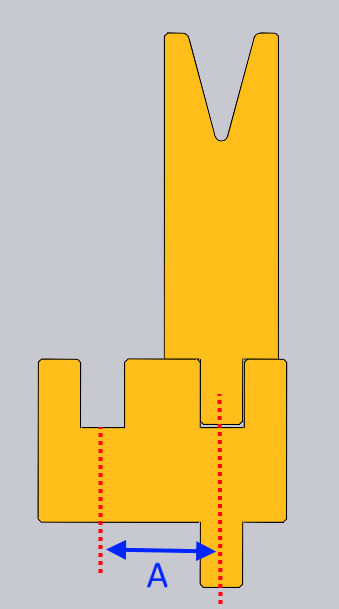
There are two parameters required to define this tool. The first (0 mm in this example) defines how far first slot, relative to holder reference is. In this case, since the first slot is aligned to the reference point the value is 0. The second parameter (36.2 mm here) which is shown as A in the image above, defines how far the second slot is from the reference point of holder.