Edit a bend
The basic settings for a bend can be viewed and edited by using the Bend panel. To bring up the bend panel for a particular bend:
-
Click on a bend in the bend navigator to select the bend.
-
Click again on the same bend to open the bend panel to edit that bend.
An alternative method:
-
Ctrl+Click on a bend in the bend navigator, to select the bend and to open the editing panel for that bend.
The Bend panel
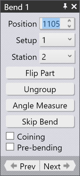
The Bend panel looks like the image alongside. This has some settings and operations for working on the bend.
-
The Position input is used to move the bend along the machine. The value displayed here is the position of the left end of the bend on the machine’s scale. (You can also drag the bend to interactively set the position, see the section below).
-
The Setup and Station lists are used to move this bend-operation to a different setup,[1] or to a different station[2] within this setup. These choices appear only if the part has multiple setups, or if the setup has multiple stations, respectively. (You can also move a bend to a different station by just clicking on the workpiece and dragging it across until it is aligned with a different station).
-
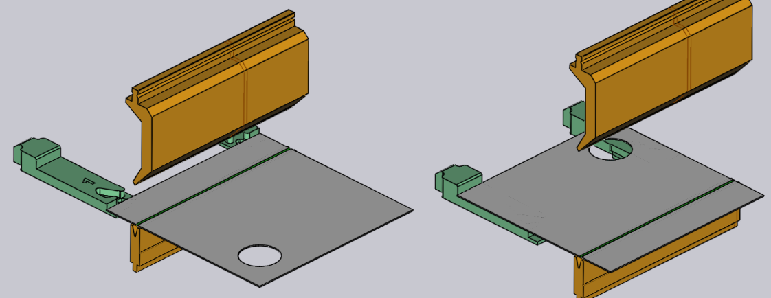
The Turn Part button is used to flip the part (insert it with the other side into the machine). The image below shows the effect of clicking this button (clicking this button again will restore the original orientation):
-
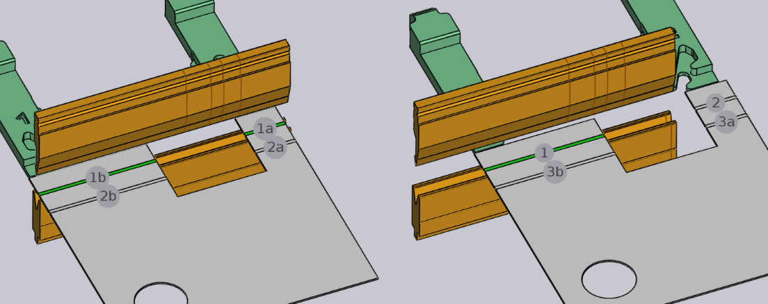
The Ungroup button appears when you are editing a multiple-span bend (a bend made of two or more collinear bending spans). If the grouped bend can be ungrouped and processed as separate bends, this button can be used to break this bend operation into two separate ones. The image below shows how bend 1 (displayed as 1a and 1b in the sequencing mode) splits into bend 1 and 2 after ungrouping:
-
The Angle Measure link is used to display the angle-measurement panel for this bend. This button is visible only if one or more angle measurement methods are available for the selected machine.
-
The Skip Bend button is used to tell Flux not to process this particular bend. This is useful to mark some bends as being processed with a different technology than the press brake (for example, a punch-press or a panel bender).[3]
-
Turn on the Coining check-box to tell Flux to use a coining operation. This is enabled only if a coining would be possible (typically, this means there is a coining-capable punch and die that can be used). Coining requires more press force but can result in a tighter bending radius than an air-bending can. Coining also requires that you have a punch and die with the exact angle that is required for this bend operation.
-
Turn on the Pre-bending option to split this bend into two separate operations — a pre-bend, and the finishing bend. By default, Flux will move the finishing bend to a position that is just after the next bend in the sequence. See the section below for more on using a pre-bend.[4]
-
Use the Prev and Next buttons to cycle through editing the different bends in the part.
Advanced operations
Here are some more advanced operations you can do with a bend.
Using a pre-bend
Some types of collisions can be avoided by splitting a bend operation into a pre-bend and a finishing bend. Here is a simple example:
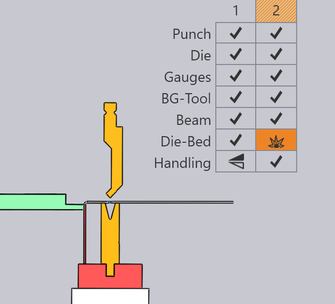
The part above has two bends, and on the second bend the part collides with the die-rail. This cannot be fixed by changing the sequence. One possible fix is to introduce a pre-bend at bend 1, by choosing bend 1 and enabling the Pre-bending check-box.
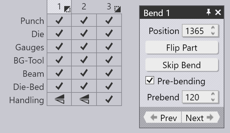
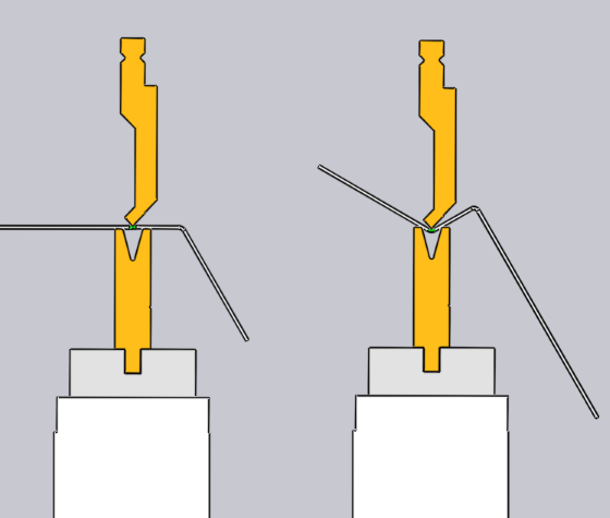
As seen in the image, this splits bend 1 into a pre-bend and a finishing-bend (which now becomes bend 3). The icons on the bend navigator now indicate that bend 1 is a pre-bend, while bend 3 is a finishing bend. You can use the Prebend input box to fine-tune the angle of the pre-bend. In this example, the angle is set to 120, so the part is bent from the flat state (180 interior angle) to 120 degrees in the first stage, and then to 90 degrees in the second stage. Thus, during the processing of bend 2, the first flange is not fully bent, and so avoids a collision with the die-rail (the images below show the situation when bends 2 and 3 are being processed):
Editing multiple bends
It is possible to edit multiple bends at the same time. To do this:
-
Click on a bend in the bend navigator to select it.
-
Hold down Shift and select additional bends to edit them all together.
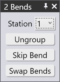
An editing panel like the one alongside is displayed. Some editing operations that can be done on all the bends together are displayed here. In addition, this panel may display some additional buttons:
-
The Group button is displayed if you select two or more bends that are collinear and could be grouped together into a single multi-span bend operation.
-
The Swap Bends button is displayed when you select exactly two bends, and allows the two bends to be swapped in the sequence (this is displayed only if the two bends can be swapped in the sequence).
-
If the two bends are parallel, in opposite directions, and are a short distance apart, it may be possible to combine them into a single Z-Bend. In this case, the Make Z-Bend button is displayed.[5]
Dragging a bend
The Position input box can be used to position a bend precisely. Often, it is easier to just drag a bend into the required position. To do this:
-
Ensure the bend editing panel is open (by clicking twice on the bend number).
-
Click on the part near the bend line and start dragging the part left/right.
Depending on where you hold the part (near the center of the bend line, or near the the left/right edges), Flux will generate automatic snap lines that help you position the bend precisely with respect to a tool station. The image below shows a bend being dragged by holding it near the center, or by holding it near the left edge.
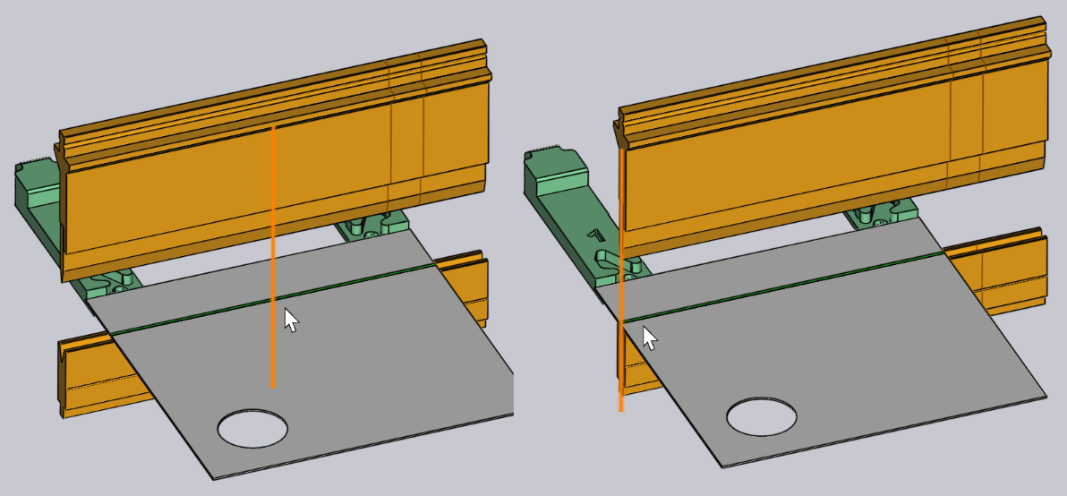
The snap lines in the figures above show the bend being positioned exactly in the center of the tool station, or with the left edge aligned exactly with the punch and die.
Editing a hem bend
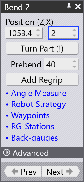
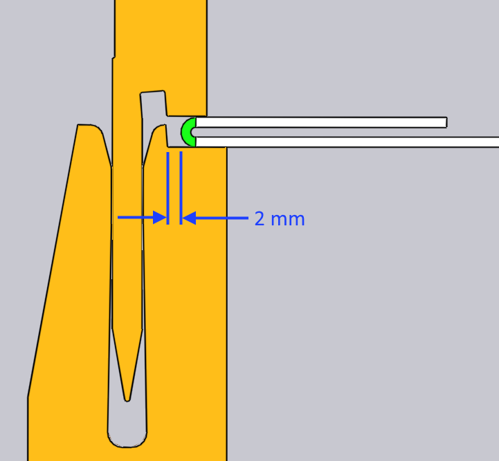
When a hem bend is processed using a bend cell, the hem edge is typically offset by a small gap. This gap is provided to prevent the hem edge from butting against the punch or die surface.
To edit this gap, open the bend panel for the hem bend and provide the value in the Position input field (in X-axis).
The default values is set to 2 mm which can be edited in the Bend defaults settings under Beam cycle. The range is from 0.1 to 10 mm.