
Repeat and sequence
Repeat grid
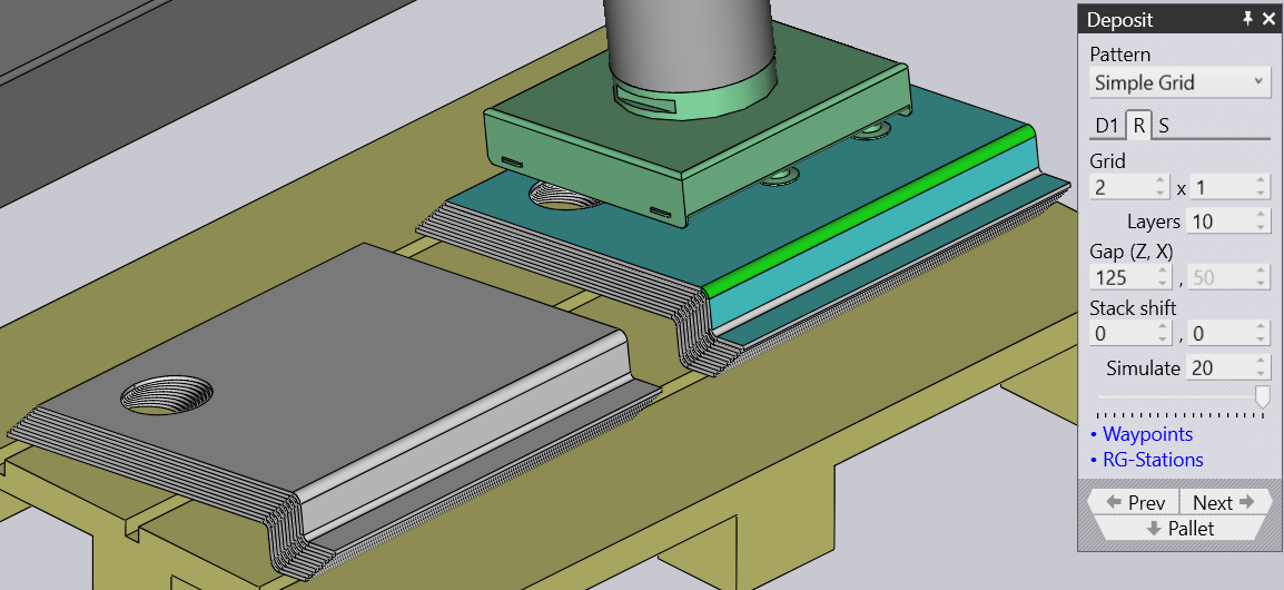
The D1 and D2 tabs shown above are used to specify the orientation of the first part of the deposit. Then, the settings in the Repeat tab are used to replicate that into a grid of rows (Z), columns (X) and layers (R). The image alongside shows a deposit with many of these settings changed from defaults.
-
The Grid settings are used to set up the number of columns and rows in the deposit.
-
The Layers setting specifies how many parts are stacked on top of each other in each pile.
-
The Gap (Z, X) settings are used to specify the gap between successive columns or successive rows. If you set this to 0, the rows or columns are exactly touching each other.
-
The Stack shift settings are used to displace the complete stack of all the parts away from the center of the pallet.
Deposit sequence
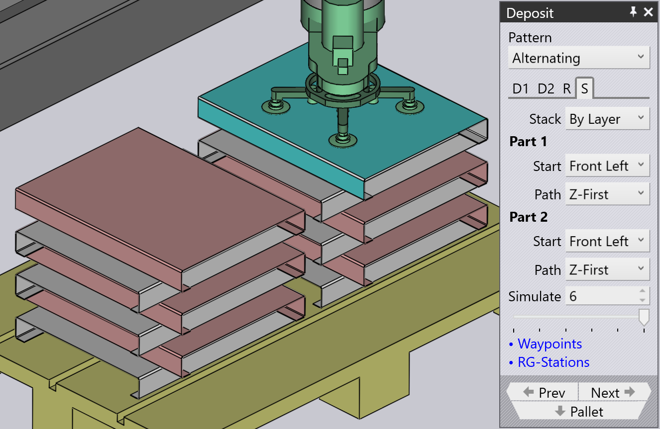
The Sequence tab is used to control the sequence in which the parts are deposited. The settings on this sequence tab are shown alongside. In this example, there are two deposit orientations D1 and D2, and there are correspondingly two sets of sequence settings (this means you can start D1 layers from one corner, while D2 layers may start from a different corner).
-
The Stack setting has two options: By Layer or By Pile. In this example here, stacking By Layer would build up both the adjacent piles in unison - this means that successive deposits would happen in pile 1, pile 2, pile 1, pile 2 etc. Thus both the piles will rise in height together. When you stack By Pile, all the parts of the pile on the left are deposited first before we start placing any parts on the right pile.
-
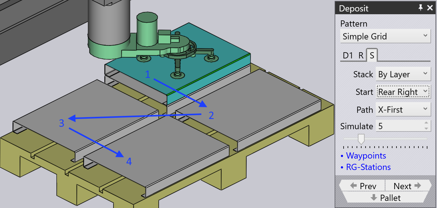
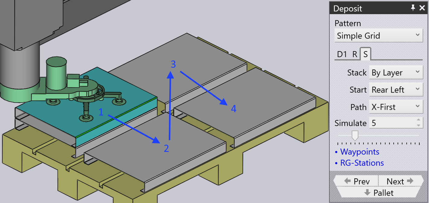
The Start corner and Path settings are used when there are multiple rows or columns, and decide which corner the stacking starts from, and whether the stacking then proceeds row-by-row, or column-by-column. This can be useful especially with an off-center gripper, since a different starting corner may cause a collision between the gripper and the previous part that was already deposited.
-
The image shows an example where we start from the Rear Right corner and proceed to deposit X-First (the numbers 1, 2, 3, 4 shows the sequence of deposits within this layer). If we started this deposit from the bottom Front Left corner (the default), we will have the situation that when we are depositing the second part in the layer, the gripper will collide with the previous part (because it extends off-center out of the part bounds).
-
The Simulate settings (both the number spinner and the slider) can be used to scrub through the deposits to see the order in which they happen on the pallet. This is especially useful when adjusting the start corner and the path settings. In the image above, we are seeing the deposit of part 17 (of 20). If we move the slider right (or adjust the value in the Simulate input box), you can view the gripper in position for deposits 18, 19 and 20.